Introduction
Responses of electrode reactions consisting of two-step electrons transfer depend on the intermediates stability 1-4. Thermodynamically unstable intermediates can be kinetically stabilized, if the second charge transfer is slow 1,2. Furthermore, the intermediate can be stabilized by the complexation with metal ions 5,6, or by the adsorption onto the electrode surface 7-10. Particularly interesting are the reactions in which the product of the first charge transfer is a radical that is only stable if it is bound to the electrode material 11-15. What is specific is that there are no dissolved radicals, and no adsorption equilibrium can be postulated. The intermediate appears in the form of an electroactive monolayer film, and its activity is proportional to the surface concentration. This mechanism is important for the electrochemistry of organic compounds, such as methanol 16-19 and formic acid 20-22, for Ru surface oxidation 23, and ammonia electro-oxidation 24. Since the charge transfers in this kind of electro-oxidation are irreversible, the responses depend on the two-steps kinetics 25. In this paper, these relationships were investigated by LSV.
Model
It was assumed that the reactant and the final product of an EE mechanism were soluble, that the intermediate was immobilized at the electrode surface, and that it could not diffuse into the solution, as shown in eqs:
For totally irreversible electron transfers at stationary planar electrodes, the mass transfer is described by the following differential equations and starting conditions (25):
The meanings of all symbols are in the Abbreviations list. Eqs. (3) and (4) were transformed into integral equations, and numerically solved 26. The solution is the relationship between dimensionless current, Φ = (𝐼1+ 𝐼2)(𝐹𝑆𝑐∗)−1(𝐷𝑣𝐹/𝑅𝑇)−1/2, and E of LSV.
In the simulation, the E increment, Δ𝐸 = 10-4 V, was used.
Results and discussion
A typical LSV response of the EE mechanism (1) and (2), with a moderately stable intermediate, is shown in Fig. 1. The second standard E is higher than the first one, but CV exhibits a single peak at 0.280 V vs. E0 1, which is close to the Ep of the second component, Ep,2 = 0.283 V. The first component Ep was 0.259 V. The kinetic parameters, 𝜆𝑠 and 𝜆𝑟, correspond to the real rate constants, k s = 10-4 cm/s and k r = 1 s-1, which means that both electron transfers were irreversible and equally slow (25). The response Ip, Φ𝑝 = 0.89, was close to the components sum Ip, Φp,1 = 0.35 and Φp,2 = 0.55.
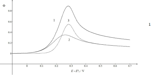
Figure 1: Dimensionless CV of irreversible two-step electron oxidation with: (1) immobilized intermediate; and its (2) first and (3) second component. E0 2 - E0 1 = 0.2 V, 𝜆𝑠 = 10-2, 𝜆𝑟 = 10-3, 𝛽1 = 0.5 and 𝛽2 = 0.5.
The first component was independent of the intermediate thermodynamic stability, but the component Ip and Ep increased with stronger second standard E. If E0 2 - E0 1 < 0 V, both components were identical, and CV was the double of the first component: Φp = 0.70 and Ep = 0.259 V vs. E0 1. Inversely, if E0 2 - E0 1 = 0.5 V, the response exhibited two peaks, due to the components separation, which is shown in Fig. 2.
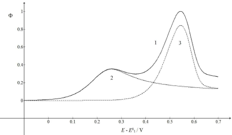
Figure 2: CV (1) and their components (2, 3), which were calculated as E0 2 - E0 1 = 0.5 V. All other data are as in Fig. 1.
The first maximum Ep appeared at 0.259 V, and the second at 0.544 V vs. E0 1. The second Ip was higher than the first one, due to the intermediate accumulation on the electrode surface. Fig. 3 shows the influence of the first kinetic parameter, 𝜆𝑠, on the LSV response of the investigated EE mechanism.
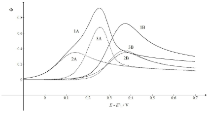
Figure 3: CV (1) and their components (2, 3), which correspond to 𝜆𝑠 = (A) 0.1 and (B) 0.001. All other parameters are as in Fig. 1.
Compared to Fig. 1, the first electron transfer was either ten times faster (A) or ten times slower (B). The rate determining step of the whole mechanism was either the second electron transfer (A) or the first one (B). If the first electron transfer was relatively fast (A), the first component Ep would be Ep,1 = 0.141 V, but the whole response Ep would be Ep = 0.253 V, which was close to the second component Ep. However, faster first steps provided intermediate higher surface concentrations, which enhanced the second component Ip. Relative slow first steps decreased the whole response. Both components Ep values were similar (Ep,1 = 0.377 V and Ep,2 = 0.371 V), and the first electron transfer dragged the second one towards higher E.
Fig. 4 shows the relationships between Ep and 𝜆𝑠 logarithm. It is seen that the first component Ep linearly depended on this argument: Ep,1 = E0 1 - 0.118 log 𝜆𝑠 + 0.023 V.
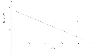
Figure 4: Ep of: (1) CV and its (2) first and (3) second component, as functions of the logarithm of the first electron transfer kinetic parameter. The straight line obeyed the equation: Ep,1 - E0 = -118 log 𝜆𝑠 + 0.023 V.
All other data are as in Fig.1.
If 𝜆𝑠 ≥ 10-2, Ep of the whole response would be determined by the second component Ep. If 𝜆𝑠 ≤ 5×10⁻³, all Ep values would be close to the straight line in Fig. 4. These limits were applied to 𝑟 = 10-3. Figs. 3 and 1 show the consequence of changing 𝜆𝑠 relative to 𝜆𝑟.
The kinetic parameter variation of the second electron transfer may have caused the appearance of the two peaks maximum response, due to the intermediate stabilization. Two examples are shown in Fig. 5 (A) and (B). If 𝜆𝑟 = 𝜆𝑠, both components peaks are similarly high and maximum at the same E. Ip in CV is a sum of the components Ip, because the intermediate was quickly oxidized, and its concentration at the electrode surface was low. The same response was obtained with the thermodynamically unstable intermediate. Also, if 𝜆𝑟 = 𝜆𝑠 and 𝜆𝑠 = 10-3 (see curves B in Fig. 3), Ip values would be identical to the ones in Fig. 5A, but Ep values were 118 mV higher. This is explained by equation (4) that defines the appearance and disappearance rates of the intermediate as a function of the difference between the first and the second current.
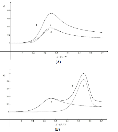
Figure 5: CV (1) and their components (2, 3), which were calculated for 𝜆𝑟 = (A) 10-2 and (B) 3×10⁻⁶.
All other data are as in Fig. 1.
The first component of the response was independent of the 𝜆𝑟 parameter, but the second one increased and shifted to 30 mV, if 𝜆𝑟 would decrease to 10-3, which can be seen in Fig. 1. By 𝜆𝑟 further reduction, second Ep was lower, as seen in Fig. 5(B). These two peaks correspond to well separated components. The second component Ep was a linear function of the second kinetic parameter logarithm: Ep,2 - E0 1 = -0.114 log 𝜆𝑟 - 0.086 V, which was applied to 𝜆𝑟 < 10-4, and tended towards 0.25 V, for 𝜆𝑟 = 10-2. The second component Ip increased with the decrease in 𝜆𝑟 value, due to the intermediate accumulation. The response shown in Fig. 5B is the same of the one in Fig. 2, which demonstrates that both thermodynamically and kinetically stabilized intermediates produced similar responses. Furthermore, by comparing 𝜆𝑠 and 𝜆𝑟 definitions, it is seen that their ratio depended on SR: 𝜆𝑠/𝜆𝑟 = (𝑘𝑠/𝑘𝑟)Δ𝐸−1(RT/FD)1/2𝑣1/2. This means that, at higher SR, the second electron transfer was slower.
Fig. 6 illustrates the possibility that the response mode can be changed by SR variation. As 𝜆𝑟 depends on 𝑣, while 𝜆𝑠 depends on √𝑣, change in 𝑣 from 10-2 V/s to 1 V/s caused 𝜆𝑟 to diminish 100 times, but 𝜆𝑠 became only 10 times smaller. Considering the relationships between the first and second component Ep and 𝜆𝑠 and 𝜆𝑟 logarithms, respectively, it is clear why the single peak response was transformed into the two peaks response under increased SR influence. The first Ip was independent from SR, while the second one increased from 0.93 to 0.99. This means that the real currents depended not only on the reactant diffusion, but also on the intermediate accumulation on the electrode surface.
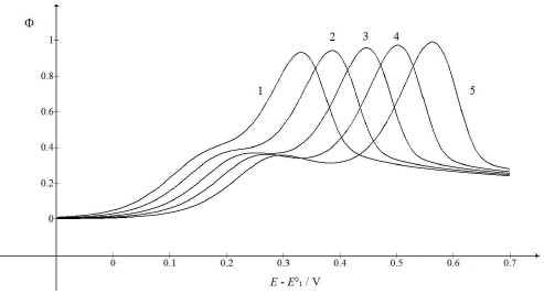
Figure 6: CV calculated for various SR. E0 2 − E0 1 = 0.4 V, 𝑘𝑠 = 10-4 cm/s, 𝑘𝑟 = 1 s-1, D = 10-5 cm2/s, ΔE = 10-4 V and 𝑣/Vs-1 = 0.01 (1), 0.03 (2), 0.1 (3), 0.3 (4) and 1 (5). All other data are as in Fig. 1.
Fig. 7 shows the relationships between the first and the second peak E of the split response and SR logarithm:
The straight lines slopes are close to theoretical values for totally irreversible diffusion controlled (2.3 RT/2𝛽1𝐹) and surface confined reactions (2.3 RT/𝛽2𝐹). If E0 2 - E0 1 < 0.3 V, the response exhibits a single peak at all SR, under the kinetic conditions in Fig. 6. E of this peak linearly depends on SR logarithm, with the slope that is the function of the intermediate stability. If E0 2 - E0 1 = 0.2 V, as in Fig. 1, the slope is 0.105 V, and if E0 2 = E0 1, it is 0.056 V.
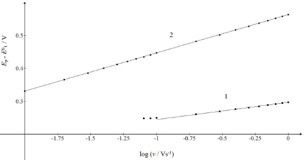
Figure 7: Dependence of the first and second maximum Ep of the split response on SR logarithm. The straight lines 1 and 2 are defined by eqs. (20) and (21).
All data are as in Fig. 6.
Conclusions
LSV of the described EE mechanism may exhibit either one or two peaks, depending on the intermediate stability. The mechanism was specific, because both electron transfers were totally irreversible, and there was no adsorption equilibrium, but the intermediate was strongly and irreversibly bound to the electrode surface. The consequence is that two electron transfers were mutually independent. The intermediate could be stabilized either thermodynamically or kinetically. Two standard E and two rate constants, as well as two transfer coefficients, were all independent variables. Hence, two current components were also independent of each other. Two steps of the mechanism could be recognized if the intermediate was stable, and two peaks would appear. The first peak originated from the diffusion-controlled electron transfer, and its Ep linearly depended on the SR square root logarithm. The second peak was caused by the surface confined electrode reaction, and its Ep linearly depended on SR logarithm. If the response did not split under the influence of an increased SR, the intermediate would be less stable, because either the difference between standard E was small, or the rate constants were high. The Ep of such response was also a linear function of SR logarithm, but the slope of this straight line depended on standard E and transfer coefficients. However, EE mechanism with an immobilized intermediate could be recognized by the fact that the first Ip was smaller than the second one, due to the intermediate accumulation. In this simple model, it was assumed that no electrode surface saturation by the intermediate occurred, because it was consumed in the second electrode reaction.
Author's contributions
Milivoj Lovrić was the solo author.
Abbreviations
cA ∗: bulk concentration of A species (mol/cm3)
cA: concentration of A species (mol/cm3)
𝑑: time increment (s)
D: diffusion coefficient (cm2/s)
E: potential (V)
E0: standard potential (V)
EE: electrochemical-electrochemical
Ep: peak potential
F: Faraday constant (C/mol)
I: current (A)
Ip: peak current
𝑘𝑠: standard rate constant of the first step (cm/s)
𝑘𝑟: standard rate constant of the second step (s-1)
LSV: linear scan voltammetry
RG: constant (j/Kmol)
S: electrode surface area (cm2)
SR: scan rate
𝑡: time (s)
T: temperature (K)
𝑣: scan rate (V/s)
𝑥: distance (cm)


