Introduction
For implant-supported fixed complete dentures (IFCD), implants are often installed between the mandibular mental foramina or the maxillary sinuses, with the most posterior implants located at the premolar region. To replace dentition and provide occlusal support up to the first molars, these full-arch prostheses have posterior free-ends, which function as a lever under occlusal loads, yielding stresses, torques, and bending moments.1-4It is common sense to reduce the distal cantilever extension as much as possible. However, its cut-off size or maximum length are still unknown as other factors, such as distal implant inclination, number and distribution of implants along the arch, prosthetic materials, and framework design, may also be associated with potential occlusal overload.5-11
Some alternative procedures for planning IFCD aim at modifying the biomechanical design to reduce strains and stresses in the prosthesis-implant-bone system. Studies reported that inclining posterior implants distally may allow better anteroposterior distribution in the arch, avoiding anatomical structures and bone grafting, as well as reducing the cantilever length.6,8,12Other studies with tilted distal implants
reduced the number of implants to simplify the technique, decrease costs, and ease cleaning.13,14 Additionally, using an angled abutment over a tilted implant could compensate for the implant inclination and align the prosthesis insertion axis with adjacent elements to facilitate the clinical procedures and laboratory fabrication.15 However, the direct biomechanical effect of these variables on stresses generated at the peri-implant bone, implant, and prosthetic components cannot be measured clinically.8,16,17
The finite element method is a computational analysis to simulate complex models that generates strain/stress in selected areas of interest where experimental or clinical methods are not feasible (e.g., implant-bone interface and internal screws).
The computational simulation requires detailed bone geometry and modeling of implant and components, material properties (modulus of elasticity and Poisson’s coefficient), and bone/implant interface, which are quite variable in the literature.18-21
Despite its limitations, the finite element method can control each variable in the simulation for a particular effect and thus help explain some empirical events to justify clinical protocols.
This study evaluated the effect of the number of implants, the distal tilting of posterior implants, and the use of angled abutments on stress magnitude and distribution in the peri-implant cortical bone, abutment screw, and prosthetic screw of mandibular IFCDs, using nonlinear finite element analysis (FEA).
Material and methods
A three-dimensional (3D) computer prototype of a human mandible was used to generate an epoxy resin model. Five external hexagon implants with a regular platform of 3.75 x 11.50 mm (OSS 311, Biomet 3i, USA) were installed axially, parallel and equidistant to each other, between the mental foramina. The implants received multi-unit screw-retained abutments (BRUA43, Biomet 3i, Brazil) with a 3-mm collar. A
full-arch IFCD was waxed-up, duplicated in acrylic resin, and reduced by 2 mm in all directions, except for the adjustment of the cylinders onto the abutments, to simulate the metallic framework. Three metal spheres were fixed to the surface to serve as reference points during the image acquisition by laser scanning.
The 3D images were superimposed, and small imperfections were corrected manually using the software Geomagic 7.0 (Raindrop, Research Triangle Park, USA). The solids of implant and prosthetic components were generated using measurements recorded with a digital caliper and an optical microscope.
The system composed of mandible, implants, abutments, and prosthesis was assembled. The prosthetic and infrastructure solids were superimposed using the cylinders as a reference point.
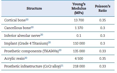
The solids set was exported to the program Rhynoceros 3D® version 3.0 (McNell & Associates, Inc., USA) to generate a continuous model for prosthesis, infrastructure, components, implants, and mandible. The FEA models were obtained by importing the meshed models to the software ANSYS 13.0 (Ansys, Houston, USA). All models were considered homogeneous, isotropic, and nonlinear. A friction coefficient of μ = 0.5 between prosthetic components was adopted.20 Table 1 shows the Young’s modulus of elasticity and Poisson’s ratio coefficient values of the materials and tissues used.22,23 In the bone/implant interface, a perfect contact between bone and implants (100% osseointegration) was assumed.
Two virtual situations were simulated:
- Straight model: All implants were axially placed and parallel to each other;
- Tilted model: The two posterior implants were inclined by 27 degrees distally, using their platform as the rotation fulcrum.
The straight and tilted models were tested by changing the number of implants (three, four, or five). In addition, the tilted model with five implants was simulated with angled abutments (27 degrees) over the two posterior tilted implants to ‘correct’ their inclination. Thus, a total of seven models were tested, models and their abbreviations are fully described in Table 2.
The bilateral insertions of the masseter muscle and the temporomandibular joints served as a fixed-point constraint set to no movement in the x, y, and z axes. A static axial load of 100 N was simulated onto the occlusal surface of the right first molar, which represented the cantilever extension (Figure 1).7
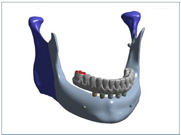
Figure 1 Three-dimensional model for simulation of the axial force applied on the first right molar (shown in red). The constraints were set as fixed points representing the masseter muscle and temporomandibular joint insertions, bilaterally (shown in blue)
The virtual load simulations on the models were analyzed to measure and compare the stress magnitude and distribution through the von Mises analysis system (maximum equivalent stress - EQV-MPa) for the cortical bone (CB), prosthetic abutment screw (AS), and prosthetic screw (PS).
ResultsFigure 8
The implant adjacent to the loading area showed the highest stress magnitudes at CB, AS, and PS for all models. Figures 2, 3, and 4 show the stress distribution and maximum peak values for the AS and PS in the models with straight abutments. Figures 5, 6, and 7 display the maximum stress peaks for each region of interest (AS and PS), per implant.
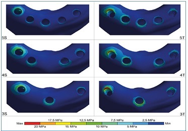
Figure 2 Stress distribution on the cortical bone under axial load at the prosthesis cantilever (right side). In all models, maximum peak stress occurred in the distal portion of the implant adjacent to the load; the anterior implant(s) had stress concentration in the anterior region. The greatest stresses were found in model 3T. The model 5S showed the most uniform distribution and the lowest stress peaks
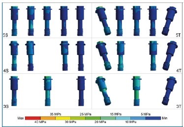
Figure 3 Stress distribution on the abutment screws under axial load at the prosthesis cantilever (right side). The screws of tilted posterior implants adjacent to the load in the 4T and 5T models had higher stress peaks near the female thread areas. The 3T model displayed a larger area of stress, with a higher magnitude, on its ‘body.’ Among straight models, the 3S model had greater stress on all abutment screws
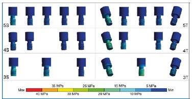
Figure 4 Stress distribution on the prosthetic screws under axial load at the prosthesis cantilever (right side). The screws of tilted posterior implants adjacent to the load had the largest stresses, regardless of the number of implants. The anterior screw showed more stress in models with three implants than in those with four and five implants, especially in model 3T
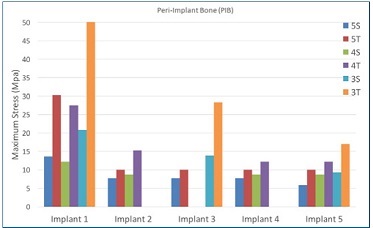
Figure 5 Maximum stress peaks on the cortical bone, in MPa, for each implant in the arch. In models 4S and 4T, implant #3 was not used; in models 3S and 3T, implants #2 and #4 were not used
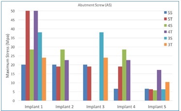
Figure 6 Maximum stress peaks on the prosthetic screw, in MPa, for each implant in the arch. In implant #1, the increase in stress peak was inversely proportional to the number of implants for straight models (5S, 4S, and 3S). Implant #1 in the 5T and 4T models showed the highest stress peaks
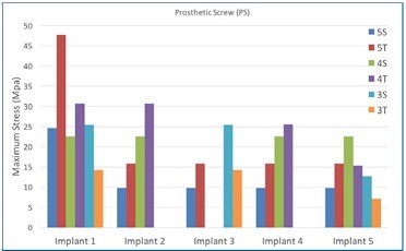
Figure 7 Maximum stress peaks on the prosthetic screw, in MPa, for each implant in the arch. In general, the tilted models displayed higher stress peaks in all implants than straight models for the same number of implants
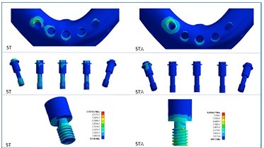
Figure 8 Comparison of stress distribution on the cortical bone, abutment screws, and prosthetic screws between the five-implant models with tilted posterior implants and straight or angled abutments (models 5T - straight abutments; 5TA -angled abutments). Angled abutments decreased the stress in cortical bone and abutment screws but increased stress in prosthetic screws
Discussion
This FEA study showed that the stress magnitude and distribution were affected by the number of implants, the inclination of distal implants, and the use of angled abutments in mandibular IFCDs. In general, the stresses in the CB, AS, and PS increased when inclining the distal implants and using three implants. On the other hand, the use of angled abutments to ‘correct’ the distal implant inclination showed mixed effects, as they decreased the stresses and strains at the bone-implant interface and in the AS but increased the stresses in the PS.
Regarding the CB, the maximum stress peaks did not vary between straight or tilted distal implants in models with either five or four implants. Although some clinical studies found no association between bone loss and distal implant angulation or cantilever length,24-27 the inclination of posterior implants was shown to reduce peri-implant bone stresses in laboratory and FEA studies.16,17,28 However, in the three-implant model, the maximum stress peaks in CB were higher than in models with four or five implants, regardless of distal implant inclination.
Moreover, the stress in ASs increased when reducing the number of implants from five to four and from five to three implants. These findings suggest a biomechanical loss when using three implants to support and retain an IFCD because the formation of a triangular polygon support is less effective than a square one to distribute the occlusal loads in the bone-implant-prosthesis system across the arch.
In addition, the use of tilted distal implants in the three-implant model substantially increased the maximum stress in the most anterior implant. The tensile forces in the anterior region result from a rocking movement generated by the load application at the cantilever, where the posterior implants act as a rotation fulcrum of compressive forces. In a clinical study using extensometers, Duyck et al.2 observed this biomechanical phenomenon and called it a ‘hinging effect.’
Sometimes the tilting of distal implants causes a divergence of the prosthesis insertion axis, making laboratory preparation difficult or impossible. One way to overcome this problem is using angled abutments to reestablish the prosthesis insertion axis closer to the ideal clinical situation or where the PSs would emerge in esthetic zones.14,15However, the stresses’ magnitudes and distribution are affected by this alternative design due to different transmission of occlusal loads to the entire system. The tilted model with distal implants ‘corrected’ by angled abutments had reduced maximum stress in CB compared to the straight model. When comparing the use of angled and straight abutments in the tilted model with five implants, in the models with angled abutments, the region near the ‘female’ portion of the AS wall closest to the loading site showed higher stresses. In models with straight abutments, there were increased stresses close to the region where this screw sits on the abutment.
Regarding the PSs, the highest stress concentration occurred in the PS close to the loading site for all models. The distal PSs on straight abutments had lower stress than those on angled abutments. Thus, the screws of straight abutments placed over inclined implants in the same axis may have less risk of loosening or fracture. A systematic review of clinical studies showed that screw and abutment loosening were frequent when using angled abutments, as well as more marginal bone loss compared to straight abutments after one year of function.29
The inclination of distal implants aims at reducing the length of the prosthetic cantilever with a simultaneous inclination and distalization of the implant platform. In IFCD, the fulcrum point for implant rotation varies according to the anatomical position of the mental foramina, bilaterally. The more ‘apical’ the foramina are, the more ‘apical’ the fulcrum point of the implant’s rotation may be. Clinically, posterior implant tilting is performed simultaneously to the distalization of the emergence of the implant platform.12-14 In this study, the posterior implants were tilted by 27 degrees distally, with the implant platform being the fulcrum point for rotation, which did not result in a displacement of the implant body. Implant distalization was not incorporated in the simulated models to avoid a new joint variable and a more complex stress interpretation. The fact that there was no distal movement of the implant platform (via implant tilting) may explain the greater stress in inclined implants.
For the models with four and five implants, tilting the posterior implants increased the maximum stresses in the AS by 100% and 150%, respectively. The stress in ASs of straight models increased as the number of implants decreased. The anteroposterior distribution of the three-implant model resulted in a larger resistance arm than the other models, but this may not be sufficient to decrease overall stresses. In this study, an approximation of anterior implants was not performed, which would provide better comparability between the positions of implants in the arch among the models tested.
Fazi et al.30 simulated models in which the anterior implants were redistributed and analyzed the effects on cortical and cancellous bone. However, in both cases (with and without anterior implant approximation), these models had only four implants parallel to one another. A configuration with implants equidistant from each other resulted in slightly lower stress magnitudes.
The literature still does not provide definitive evidence of the tolerable stress limits for each part of the bone-implant-prosthesis system without clinical harm. Accordingly, the
present study’s findings should be carefully evaluated as the degree of stress that may cause any mechanical failure (loosening or fracture of prosthetic components or implants) or biological failure (peri-implant bone resorption or osseointegration failure) is unknown. Recent systematic reviews reported no association between the number of implants used to support IFCDs and survival rates of implant and prosthesis, complications, or bone loss in studies with follow-ups ranging from 1 to 15 years.31-33 However, most of the clinical studies included were heterogeneous and did not address the primary question of the number of implants with standardized methods, and the biological conditions, such as occlusal force and quantity and quality of bone, were not controlled. For example, an FEA study on the influence of bone quality on stress distribution in IFCD showed that the less compact bones (poor bone quality) increased the stresses in implants and prosthetic superstructure and decreased the stresses in trabecular bone.19
Ferreira et al.34 aimed to validate a numerical model that could be used to study stresses and strains created in the different components involved in oral fixed rehabilitations through FEA and static compressive load test (SCLT). Analyzing the tendencies of both models, an absolute match of their biomechanical behaviors can be observed, validating the computational model. However, such findings are more easily transposed to mechanical failures since biological tissues, such as bone tissue, are reproduced in simulation studies that are quite controversial, requiring clinical studies.
The distribution and magnitude of stresses result from a complex combination of mechanical and biological factors that interact simultaneously. The finite element method enables simulation of forces applied to selected structures, but some model simplifications are required. The present study used a nonlinear finite element method with a friction coefficient of 0.5 to improve the accuracy in simulating the relationship among implant and prosthetic components.20 In the bone/implant interface, a 100% osseointegration was adopted because the anterior mandible has high bone density,20,22,30
despite uneven contact between bone and implant.18 Therefore, the results of FEA studies should be interpreted with caution and cannot be directly extrapolated to the clinical practice.
Although it is impossible to completely reproduce the clinical situation, the FEA method is useful to understand the effect of isolated factors in prosthesis design. Thus, the present findings may help clinicians carefully evaluate the patient’s conditions to plan the treatment with IFCD, lowering biomechanical risks accordingly. Furthermore, it can provide subsidies for the control of variables in future clinical studies.
Conclusions
Within the limitations of this study, the findings suggest that:
• Von Mises strains/stresses in the CB, ASs, and PSs increase when tilting the posterior implants and reducing the number of implants;
• The use of angled abutments over tilted implants can reduce the stresses in CB and abutment screws, but its prosthetic screws are more stressed than in straight abutments.


