Serviços Personalizados
Journal
Artigo
Indicadores
-
 Citado por SciELO
 -
 Acessos
Links relacionados
-
 Similares em
SciELO
Compartilhar
Portugaliae Electrochimica Acta
versão impressa ISSN 0872-1904
Port. Electrochim. Acta vol.31 no.3 Coimbra maio 2013
https://doi.org/10.4152/pea.201303175
Effect of Cathode Materials on Electrochemical Degradation of Luganil Blue N and Acid Red I
P. Sarala and T.V. Venkatesha*
Department of PG Studies & Research in Chemistry, School of Chemical Sciences, Jnana Sahyadri, Kuvempu University, Shankaraghatta-577451, Shimoga, INDIA
Abstract
The degradation of Acid Red I dye (ARI) and Luganil Blue N (LBN) has been studied by electrochemical treatment methods. The efficiency of cathode materials such as platinum, copper, zinc, lead, graphite, nickel, steel and titanium metals on the degradation of Luganil Blue N and Acid Red I dyes were investigated. The suitable cathode material was chosen and other parameters such as current density, and NaCl and dye concentrations were optimized. The electrolysis process was monitored by UV- Vis spectrophotometer and measuring chemical oxygen demand of the electrolyzed solutions. The overall COD removal efficiencies reached as high as 74.24% and 87% for ARI and LBN, respectively.
Keywords: current density, electrolysis, cathode material, Luganil Blue N dye, Acid Red I dye.
Introduction
The textile, leather, paper and pharmaceutical industries are the major users of synthetic dyes and produce large amount of waste water containing these dyes. Generally, dyes are stable and difficult to degrade by biological methods leading to severe water pollution [1]. The removal of these dyes from waste water is a challenge for researchers. Various treatment methods (biological, physicochemical, photolytic, ozonation, Fenton, electrochemical, wet air oxidation, etc.) have been developed, being presently employed effectively for the treatment of dye effluents [2-6]. Among all of them, the electrochemical technique is found to be an interesting method, environmental friendly, and without causing any secondary pollution.
Different electrochemical methods such as electro-Fenton [7-8], electrocoagulation [9], electro flocculation and electro-oxidation [10] (direct and indirect electro-oxidation) are used for the treatment of various types of effluents. Among these treatments, indirect electro-oxidation also shows good efficiency in removing the organic pollutants in a shorter time. The distinct feature of the electrochemical method involves the generation of a wide variety of oxidants like OH•, H2O2, HOO•, O3 Cl2, HOCl, etc. The chloride based radicals are produced in situ at the electrodes by the oxidation of Cl -ions and these oxidants oxidize the chromophoric groups of the dyes making the waste water free from colour. Also these oxidants oxidize some of the functional groups, and the double bonds of these dyes consequently bring down the COD of the waste water. The following mechanism for generation of oxidants has been given in many research publications [11-12]:


The formation of these oxidants depends on the type of electrodes employed as anodes. The large number of materials such as Pt, graphite, ACF (Activated Carbon Fiber), RuO2, SnO2, PbO2, and Boron Doped Diamond (BDD), are used as electrodes (anodes) [13-22] which produce strong oxidants in order to oxidize the organic compounds. Ricardo E. Palma-Goyes et al. [23] have reported the electrochemical degradation of crystal violet with BDD electrodes; del Rio et al. [24] have studied the behavior of Ti/SnO2-Sb-Pt for the treatment of reactive dyes; and also Miao Li et al. [25] evaluated the two typical electrodes Ti/RuO2-Pt and Ti/IrO2-Pt for the treatment of phenol. These electrodes show extraordinarily good results. But the electrochemical method with low cost electrodes remains a major goal. Therefore, there is growing interest in using materials viz. carbon [26], Pt, iron [27] and aluminum [28] that have been tested. Carbon fiber electrode shows good efficiency with the Fenton's reagent [29].
In earlier studies [30], the effect of the polarity of the working electrode on the degradation efficiency was discussed; when the polarity changed to cathode played an important role in achieving good degradation efficiency. So the present study is aimed to select the suitable cathode material in order to achieve high degradation efficiency.
Experimental
Reagents
All chemicals were of analytical grade and were used without purification. The Luganil Blue N (LBN) (C.I. Acid blue 193) with molecular formula (C40H24N4CrNaO10S2) [F.W. 858] and the Acid Red I (ARI) dye with molecular formula C18H13N3O8S2.2Na [F.W. 509.43], purchased from Sigma Aldrich (Bangalore, India), were used in this study.
Electrolysis
100 mL of aqueous solution of both LBN and ARI dyes (100 mg L-1) were used for experiments. The NaCl was used as supporting electrolyte. Electrolysis experiments were conducted in an undivided cell containing the working electrode and the counter electrode. The saturated calomel electrode was used as reference. Prior to each electrolysis experiment the electrodes were dipped in dil HCl for few minutes and then washed thoroughly with double distilled water. The solution was subjected to stirring by a magnetic stirrer with the speed of 500 rpm.
The distance between the working electrode and the counter electrode was 0.5 cm. A potentiostat/galvanostat (Model PS-618 Chemilink Systems, Mumbai, India) was used as DC source for the electrolysis. The influence of different cathodes such as platinum, copper, zinc, lead, graphite, nickel and titanium, on the degradation of LBN and ARI was studied.
Analysis methods
Cyclic voltammetry measurements were done at room temperature with a conventional three electrode cell using a computer controlled electrochemical work station (CH Instruments 660C USA). A micro platinum electrode as working electrode and a platinum wire as auxiliary electrode were used. The UV- Vis spectrophotometer (UV-1650 PC SHIMADZU) was used for recording the spectra of dye solutions electrolyzed under different conditions. The chemical oxygen demand (COD) was measured by adopting standard procedure (Open reflux Method) [31].
The relative removal of colour as well as COD was calculated using equation (1),

If X is the colour removal, then A1 is the absorbance value of untreated dye solution at 579.5 nm, and AX is the absorbance value of the treated dye solution. If X is the COD removal, then A1 is the initial COD value of the solution before electrolysis and AX is the final COD value of the solution after electrolysis.
To see the influence of cathode materials, the preliminary electrolysis experiments were conducted using a solution of 2 g L-1 NaCl and 100 mg L-1 dye at current densities of 25 mA cm-2 for ARI, and 50 mA cm-2 for LBN dye with electrolysis time ranging from 0 to 120 min.
To see the influence of the current density, the preliminary electrolysis experiments were conducted using a solution of 2 g L-1 NaCl, taking Cu as working electrode and 100 mg L-1 dye at current densities of 4, 13 and 25 mA cm-2 for ARI, and of 10, 30 and 50 mA cm-2 for LBN with electrolysis time ranging from 0 to 120 min.
The NaCl concentration was varied from 2 g L-1 to 6 g L-1 keeping the initial dye concentration at 100 mg L-1 and the current density at 25 mA cm-2 for ARI and 50 mA cm-2 for LBN. For each concentration of NaCl, the electrochemical treatment was carried out at different time intervals starting from 10 to 120 minutes.
Further experiments were conducted using solutions with dye concentration from 50 mg L-1 to 200 mg L-1 keeping NaCl concentration of 2 g L-1 and the current density at 25 mA cm-2 for ARI and 50 mA cm-2 for LBN with electrolysis time from 0 to 120 min.
Results and discussion
Effect of electrodes
The influence of cathodes on the degradation rate of both dyes (ARI and LBN dye) was studied. The anode was platinum and the electrolysis was carried out using different cathodes. The electrolyzed solutions were used to measure the absorbance in the UV-Vis range. Fig. 1a and 1b are the UV-Vis absorbency spectrograms in the wavelength range 200 to 800 nm.
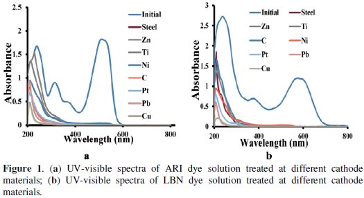
Two types of peaks were noticed in the visible and UV region. The only one peak in the visible range was noticed for both dyes and is due to azo group.
The ARI dye shows three peaks with gradual increase in intensities with decrease in wavelength in the UV region. Whereas LBN dye shows only two peaks in the UV region. These peaks are due to the groups other than azo groups. The peaks at 515 nm and 578 nm in the visible region correspond to ARI and LBN dyes, respectively.
After electrolysis the peak intensities of electrolyzed solution in the visible region decrease to zero for cathodes Cu, Pb, Pt, indicating complete removal of colour. Whereas for steel, zinc, titanium, nickel and graphite cathodes, 93 to 97 % colour removal was noticed. Also peaks at 375 and 230 nm of LBN, and 314 and 238 of ARI dyes were decreased in the order copper, lead, platinum, graphite, nickel, titanium, zinc and steel.
The variation of COD removal with electrolysis time for the different cathodes is shown in Fig. 2a and 2b.
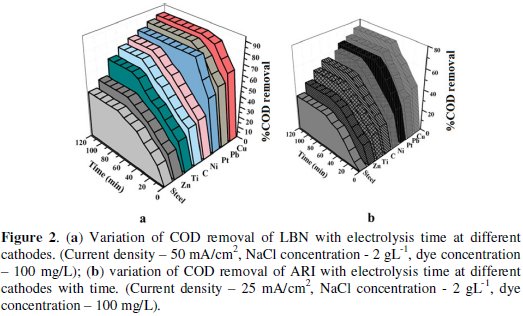
For the Cu electrode, not only the rate of degradation of dyes (ARI and LBN) is faster but also higher rate of COD removal is achieved. At Cu electrode as cathode, 87% COD removal for LBN dye and 74% COD removal for ARI dye were achieved with electrolysis time of 70 and 50 min, respectively. But 43%, 50%, 65%, 72%, 76%, 80% and 84% (LBN) and 33%, 42%, 50%, 56%, 66% and 69% (ARI) of COD removal was obtained at lead, platinum, graphite, nickel, titanium, zinc and steel electrodes.
From the results one can infer that the maximum degradation was observed at Cu electrode for both the dyes. Even though the electrochemical oxidation of organics depends on the type of anode materials, the cathode materials also play a role in enhancing the degradation. This may be due to the good electro catalytic property of copper, i.e., it reduces the dissolved oxygen present in the dye solution to produce H2O2, a good oxidant which enhances the oxidation reaction to occur at higher rate, or may be higher cathodic reaction takes place at copper which forces the anodic reaction to take place at higher rate compared to other cathodes. Hence it indirectly supports the anode and makes the electrochemical oxidation reaction to proceed at faster rate.
So in the present case the rate of oxidation reaction was accelerated when Cu was used as cathode. Among all electrodes, Cu was considered as the best cathode material for the present electrochemical investigation and it was used for further studies.
Effect of current densitys
In electrochemical degradation studies the current density is key design parameter and process manipulator of electrochemical applications. In order to assess the effect of applied current density on the rate of COD removal, another set of experiments was carried out with Cu electrode as cathode and varying current densities ranging from 4-25 mA cm-2 for ARI and 10-50 mA cm-2 for LBN dye.
Fig. 3a and 3b show the effect of current densities on the rate of COD removal obtained during electro chemical degradation of ARI and LBN dye solutions.
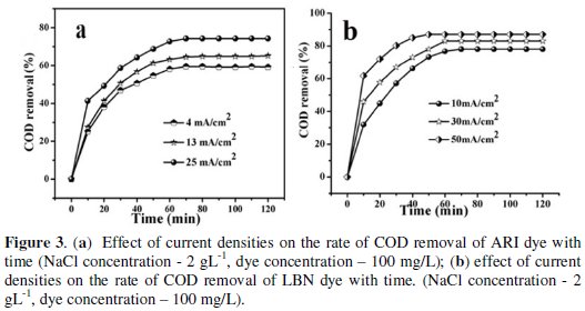
Each curve in both figures shows three types of variation with respect to time for a given current density. In the first stage COD removal proceeds at faster rate, i.e., within 10 minutes, but in the second stage up to 60 min of electrolysis a gradual rise in rate of COD removal was noticed. In the final stage it reaches a limiting value of 74% COD removal for ARI at 25 mA cm-2 and it was 87% at 50 mA cm-2 for LBN dye. Further at higher current densities a slight increase in solution temperature was noticed. For further studies the current density was fixed at 25 mA cm-2 for ARI dye and 50 mA cm-2 for LBN dye as the optimum current densities.
Effect of electrolyte concentration
Generally, addition of a salt to the solution increases the conductance. In many of the electrochemical treatment processes, a supporting electrolyte is added and its use provides many advantages, i.e., increases conductance, brings down the operating voltage besides a source for free radicals. In this investigation NaCl was taken as supporting electrolyte, the operating conditions were similar to those as above. To see the effect of NaCl its concentration was varied from 2 g L-1 % to 6 g L-1 %. Fig. 4a and 4b present the effect of NaCl on the degradation rate of LBN and ARI dyes and on the COD removal.
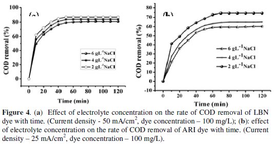
A general trend was observed for both dyes, an increase of the COD removal with increasing the electrolyte concentration up to 2 g L-1, above which there was no additional effect of NaCl.
In other words, the maximum degradation of both ARI and LBN dyes and COD removal was achieved at 2 g L-1 NaCl.
The higher concentration of chloride ions was not favourable for greater mineralisation. At higher concentration of NaCl, more chloride based radicals were produced at the vicinity of the anode and these radicals are capable of cleaving the -N=N-, azo group which is the most active site of dye molecule rather than the aromatic as well as the aliphatic linkages [32]. Hence the decolourisation of dye takes place at faster rate. However lower COD removal at higher concentration of NaCl indicated that, only less number of hydroxyl and other related radicals are produced which are known to oxidize the aromatic and aliphatic linkages leading to lower value of COD.
Effect of initial dye concentration
On account of the fact that the industrial wastewater usually contains different concentrations of azo dyes, it is very significant, from a practical point of view, to study the effect of the initial concentration of dye on the performance of the electrochemical degradation process for the removal of pollutants. Fig. 5a and 5b show the effect of concentration of dye on the degradation.
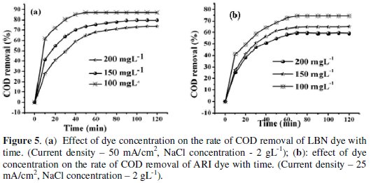
It was observed that the degradation decreased from 74% to 59% as the concentration of dye increased from 100 mg L-1 to 200 mg L-1 for ARI and 87% to 73.6% for LBN. Correspondingly, the amount of COD removal increased sharply at low concentrations of dyes.
The decreasing trend of decolourization and degradation efficiencies at higher dye concentrations may be due to the combined effects of increased dye concentration and decreased transparency of dye solution and in addition increase in dye concentration utilizes more and more oxidants which results in low rate of degradation of dye.
Conclusions
ARI and LBN dyes can be degraded by using Cu electrode as cathode with appreciable COD removal. The electrochemical property of cathode material affects remarkably the reaction rate for both the dyes. The reaction rate is reasonably higher on the Cu electrode, while the reaction rate is relatively slow on the Pb, Pt, C cathodes and the slowest on the steel cathode. However the rate of reaction is in the order of Steel < Zinc < Titanium < Nickel < Graphite < Platinum < Lead < Copper. The optimized conditions for the present degradation process are 25 mA/cm2 current density for ARI and 50 mA cm-2 current density for LBN, 2 g L-1 NaCl concentration, 100 mg L-1 dye concentration. The maximum COD removal of 74.24% and 87% was achieved for ARI and LBN respectively.
References
1. Jin R, Yang H, Zhang A, et al. J Hazard Mater. 2009;163:1123-1128. [ Links ]
2. Zainal Z, Lee CY, Hussein MZ, et al. Dyes Pigments. 2008;76:440-446. [ Links ]
3. Carvalho C, Lopes A, Pinheiro H, et al. Chemosphere. 2007;67:1316-1324. [ Links ]
4. Wang A, Qu J, Liu H, et al. Chemosphere. 2004;55:1189-1196. [ Links ]
5. Sakalis A, Vanerkova D, Holcapek M, et al. Chemosphere. 2007;67:19401948. [ Links ]
6. Awad HS, Galwa NA. Chemosphere. 2005;611327-1335. [ Links ]
7. El-Desoky HS, Ghoneim MM, El-Sheikh R, et al. J Hazard Mater. 2010;175:858-865. [ Links ]
8. Kayan B, Gozmen B, Demirel M, et al. J Hazard Mater. 2010;177:95-102. [ Links ]
9. Kobya M, Demirbas E, Dedeli A, et al. J Hazard Mater. 2010;173:326-334. [ Links ]
10. Chatzisymeon E, Dimou A, Mantzavinos D, et al. J Hazard Mater. 2007;167:268-274. [ Links ]
11. El-Ashtoukhy E-SZ, Amin NK. J Hazard Mater. 2010;179:113-119. [ Links ]
12. Rajkumar D, Song BJ, Kim JG. Dyes Pigments. 2007;72:1-7. [ Links ]
13. del Rio AI, Molina J, Bonastre J, et al. J Hazard Mater. 2009;172:187-195. [ Links ]
14. Awad YM, Abuzaid N. Separ Sci Technol. 1999;34:699-708. [ Links ]
15. Fan L, Zhoub Y, Yang W, et al. J Hazard Mater. 2006;137:1182-1188. [ Links ]
16. Panizza M, Bocca C, Cerisola G. Water Res. 2000;34:2601-2605. [ Links ]
17. Montilla F, Morallon E, Vazquez JL. Electrochim Acta. 2002;47:4399-4406. [ Links ]
18. Szpyrkowicza L, Kaulb SN, Netib RN, et al. Water Res. 2005;39:1601-1613. [ Links ]
19. Perret A, Haenni W, Skinner N, et al. Diam Relat Mater. 1999;8:820-823. [ Links ]
20. Montilla F, Michaud PA, Morallon E, et al. Electrochim Acta. 2002;47:3509-3513. [ Links ]
21. Chen XM, Chen GH, Gao FR, et al. Environ Sci Technol. 2003;37:5021-5026. [ Links ]
22. Saez C, Panizza M, Rodrigo MA, et al. J Chem Technol Biot. 2007;82:575-581. [ Links ]
23. Palma-Goyes RE, Guzman-Duque FL, Penuela G, et al. Chemosphere. 2010;81:26-32. [ Links ]
24. del Rio AI, Fernandez J, Molina J, et al. Electrochim Acta. 2010;55:7282-7289. [ Links ]
25. Li M, Feng C, Hu W, et al. J Hazard Mater. 2009;162:455-462. [ Links ]
26. Ya X, Strunk PJ, Xia H, et al. Water Res. 2001;35:4226-4230. [ Links ]
27. DeFazio SAK, Lemley AT. J Environ Sci Heal A. 1999;34:217-240. [ Links ]
28. Kobya M, Can OT, Bayramoglu M. J Hazard Mater. 2003;100:163-178. [ Links ]
29. Jia J, Yang J, Liao J, et al. Water Res. 1999;33:881-884. [ Links ]
30. Sarala P, Venkatesha TV. Environ Technol. 2011;32:1939-1945. [ Links ]
31. Clesceri LS, Greenberg AE, Eaton AD. 20th ed. Washington DC:APHAAWWA-WPCF;1998. [ Links ]
32. Songa S, Fana J, Hea Z, et al. Electrochim Acta. 2010;55:3606-3613. [ Links ]
Acknowledgements
The authors are grateful to the authorities of the Dept. of Chemistry, Kuvempu University for providing lab facilities.
*Corresponding author. E-mail address: drtvvenkatesha@yahoo.co.ukn
Received 7 February 2013; accepted 20 May 2013


