Serviços Personalizados
Journal
Artigo
Indicadores
-
 Citado por SciELO
 -
 Acessos
Links relacionados
-
 Similares em
SciELO
Compartilhar
Portugaliae Electrochimica Acta
versão impressa ISSN 0872-1904
Port. Electrochim. Acta vol.32 no.1 Coimbra jan. 2014
https://doi.org/10.4152/pea.201401065
Removal of Lead from Industrial Wastewater Using Flow-by-Porous Electrode
Omar E. Abdel-Salama , Ibrahim M. Ismaila,* , Ahmed Solimana , Ahmed A. Afifya and Hanaa M. Alyb
a Chemical Engineering Department, Cairo University, Giza, Egypt
b Chemical Engineering & Pilot Plant Department, National Research Center, Dokki, Egypt
Abstract
Lead present in several industrial wastes has deleterious effects on the quality of water. Cathodic deposition has been considered as one of the suitable means for lead removal. Experiments were carried out using a lab-scale electrochemical cell incorporating flow- by porous graphite electrodes at steady state conditions. The effects of flow rate, current density, lead influent concentration and pH, on lead removal efficiency, current efficiency, lead removal rates, and cell potential, were investigated. It was found that the maximum removal efficiency (97.75%) was obtained at flow rate (100 mL/min), for initial concentration (40 mg/L), with a residual concentration (0.9 mg/L) and maximum current efficiency of (60.7%). In addition, the recovery of lead from wastewater was investigated.
Keywords: cathodic deposition; flow-by porous electrode; current efficiency; removal efficiency.
Introduction
Heavy metal pollution is an environmental problem of worldwide concern. Heavy metals released into the environment have been increasing continuously as a result of industrial activities and technological development [1].
Important toxic metals, i.e., lead (Pb), cadmium (Cd), zinc (Zn), and copper (Cu) find their way to the water bodies through industrial wastewater streams [2]. The release of large quantities of heavy metals into the natural environment, e.g., irrigation of agricultural fields by using sewages has resulted in a number of environmental problems [3] and due to their non-biodegradability and persistence, can accumulate in the environment elements such as in food chain, and thus may pose a significant danger to human health [4]. Pb heads the list of environmental threats because, even at extremely low concentrations, it has been shown to cause brain damage in children [5].
A number of techniques have been used to remove the metal ions from wastewater effluents; including chemical precipitation [6], ion exchange process [7-17], electrolytic methods [18-20], adsorption onto activated carbon [21, 22], low cost adsorbents such as kaolin, bentonite, blast furnace slag and fly ash [23 ], ion imprinted polymer (IIP) [24-26], organic-based ligand precipitation [26], membrane and reverse osmosis processes [28]. The industrial utilization of these methods has been found to be limited, because of the high capital and operating costs and/or the ineffectiveness in meeting stringent effluent standards. The environmental sciences have experienced enormous progress in the last several years. The necessity of planning the rational use of energy and water resources has provided a challenge to the applied sciences and engineering to develop new technologies, new processes and new materials for pollution prevention and control. This is also a consequence of the increasing legal pressures that are forcing industry to accept responsibility for waste treatment or storage in an attempt to minimize pollution.
The increasing use of electrochemical technologies in a variety of applications such as synthesis [29], energy storage and environmental treatment is due, among other reasons, to the utilization of porous materials as three dimensional electrodes in the design of electrochemical reactors [30]. One of the main advantages of this kind of electrode derives from the fact that it can provide high specific surface area as well as high mass transfer rate. It is optimal to operate the porous electrode at the maximum rates everywhere within the bed. This is an ultimate goal in operating a flow-through porous electrode. However, porous electrodes frequently operate with non-uniform reaction rates, resulting in lower extents of utilization of the bed [31].
Flow-by porous electrode works as flow-through porous electrode, but the difference between them is that the electric current flows perpendicular to that of the electrolyte (in case of flow-by). Previous results show that the flow-by configuration is superior, because the system yields a greater return on investment, and also offers the operational flexibility of variable flow rate and conversion [32].
Alkire and Ng [33, 34] have modeled the cylindrical geometry of the flow-by configuration. Their model, which was specifically applied to metal-ion removal, assumed two-dimensional concentration variations in the absence of axial diffusion and dispersion and complete Butler-Volmer kinetics.
Ju Chung and Pak [35] concluded that the electrochemical reactors incorporating flow-by porous electrodes can provide a powerful method in metal recycling. In cathodic reaction, metal ions are reduced and deposited on the porous electrode. Therefore, several types of electrochemical cells can be used to remove the metal from wastewater, especially in small-scale industries operating in communal areas where there is a need to find easy and reliable methods for wastewater treatment [35]. Porous materials such as carbon and graphite felt have been used as electrodes in various electrolysis cells, because of their high specific surface area and high conductivity [36]. Such materials have also been successfully employed for lead ion removal from dilute solutions. The key parameters for the removal of metal ions from wastewater streams are the current density and flow velocity [36].
The use of flow-by porous electrodes for the treatment of industrial wastewater has been studied by Pletcher and Ponce de Leon [37]. In their work, the removal of lead ions from aqueous solution of lead nitrate at pH of 2 has been investigated in a cell with a reticulated vitreous carbon cathode. There remains a high level of interest in technology for removing lead from effluents, waters and process streams to level &tt; 1 ppm. In the present work, different cell dimensions, different flow rates, porosity of the electrode bed and steady state case will be investigated.
Materials and methods
The main part of the experimental apparatus used is the electrochemical cell is shown in Fig. 1.
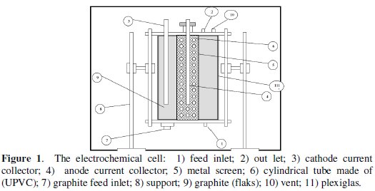
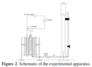
It is consisted of two co-axial Plexiglas cylinders with 10 and 20 cm inner diameters fixed to end flanges. The anode is contained in the inner cylinder, whereas the cathode is contained in the annular space between the two cylinders. The feed solution entered through an opening at the bottom of the cell and flow. The outlet of the flow was located at the upper flange of the cell. Two stainless steel rods (D = 8 mm, L = 400 mm) were used as current collectors. A vent was also located at the top flange for the release of accumulating gases. Graphite powder passing sieve no. 16 and retained on sieve no. 200 was added to the cell and used to fill each compartment. The cell current was supplied by a DC power type farneII LT30-2. Cell current and potential were measured using multimeters types M3800 and DT 830, respectively. The feed solution was supplied from a constant head tank 20 liter in volume placed at 2 meters above the base of the cell. The flow through the bed was by gravity and was controlled by a needle valve. The flow rates were determined by using a graduated cylinder to collect certain volume of the effluent in a given time. The samples were taken after two times of the residence time, as suggested previously by Leon and Pletcher [37], to ensure that steady state conditions are reached. A schematic of the experimental setup is shown in Fig. 2.
Experiments were carried out using different solutions. Solution (a): 0.5 M NaNO3 contains 5 mg/L lead, as Pb(NO3)2; solution (b): 0.5 M NaNO3 contains 20 mg/L lead, as Pb(NO3)2; solution (c): 0.5 M NaNO3 contains 40 mg/L lead, as Pb(NO3)2. All solutions were prepared from annular grade chemicals and were dissolved in de-ionized water. In all cases, pH was adjusted at 2, 4, and 6, respectively, by using nitric acid (68% conc.). The pH was measured by a pH-meter Schott CG710. The lead concentration in the effluent was determined by an atomic absorption spectrophotometer model (GBC 902). Standard spectrosol 1000 Pb(II) solution was used for the calibration.
Results and discussion
The effects of flow rate, initial concentration, feed, pH, and cell current density on, lead removal efficiency, current efficiency, and cell potential are described and discussed below.
Effect of flow rate on the removal rate
Removal rate (R) is the rate of lead ion deposition on the surface of cathode per second, and it is calculated from the equation:

where Q is the flow rate, Ci and Co are the lead concentration of influent and effluent respectively. The relation between the feed flow rate and the removal rate of lead at constant concentration is illustrated in Fig. 3.
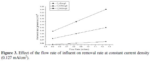
These results indicate that the removal rate increases as the feed flow rate increases, and they are in good agreement with Newman [1975], who observed that the removal process at this concentration level is mass transfer controlled.
Effect of the flow rate on removal efficiency of lead
Removal efficiency is defined as the percentage of lead in the influent solution which is removed at the cathode. Fig. 4 shows the influence of the flow rate on the removal efficiency.
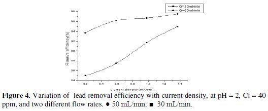
It is obvious that when the flow rate increases at the same current density, for the same initial concentration the removal efficiency increases. This observation is explained by the fact that high flow rate increases the mass transfer coefficient, which in turn increases the amount of lead deposited on the surface of the cathode. Similar results were obtained by Sarfarazi and Ghoroghchian [38] during the study of the removal of copper on carbon flow-by electrode.
Effect of initial concentration on the removal rate
The effect of the inlet concentration on the removal rate of lead at cell current density of 0.127 mA/cm2 is shown in Fig. 5.
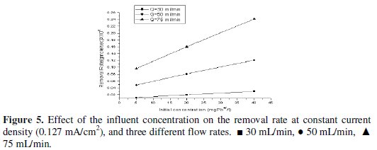
It is observed that the removal rate increases with increasing the initial concentration. This result supported the previously concluded fact that the removal process is mass-transfer controlled.
Effect of initial concentration on the removal efficiency of lead
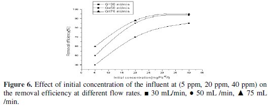
Fig. 6 shows the influence of lead concentration on the removal efficiency. It is clear that as the initial concentration increases the removal efficiency increases.
Effect of pH on removal rate and removal efficiency
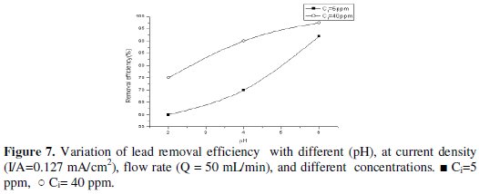
The effect of pH of influent on the removal rate was studied as lower pH is expected to increase the rate of hydrogen evolution. The data, obtained and shown in Table 1, indicate that at the same current density the removal rate decreases with decrease in pH.

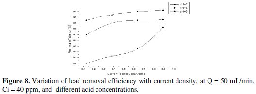
This is explained by the fact that, at lower pH, the rate of hydrogen evolution increases. This is expected to decrease the fraction of current available for lead removal but, because of the increase in mass-transfer coefficient with hydrogen evolution, this effect is less pronounced. However, at higher potential and lower pH the main reaction was proton reduction, producing hydrogen which accumulates on the carbon felt surface and therefore interferes with the deposition of lead ion. For this reason, the removal efficiency increases with slightly increase in pH, as shown in Figs. 7 and 8.
Effect of applied current on current efficiency
At the surface of the cathode, the lead deposition may be accompanied by a hydrogen evolution. The individual contribution of each reaction is given by its current efficiency and may be calculated by Faraday's law. The current efficiency was calculated from the following:
% Current efficiency = current equivalent to the deposition rate of lead / total cell current x 100%
where, the current equivalent to the deposition rate of lead, I, was calculated from the relation:

where I is the electric current, F is Faraday's constant = 96500 coulombs/gequivalent, n is the number of electrons in the electrode reaction, R is the flow rate (mL/sec) and Ci, Co are influent and effluent concentration of lead in (g-mol/ mL).
Table 2 shows the effect of applied current density on current efficiency at constant initial lead concentration of 40 mg/L, and at different flow rate and constant pH of inlet solution (pH = 2).

From Fig. 9 it is obvious that the current efficiency decreases as applied current density increases.
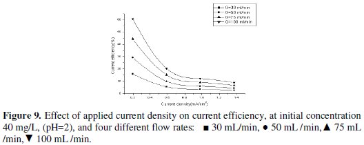
The current efficiency reaches a maximum value of 60.6% at 0.195 mA/cm2 current density for feed flow rate of 100 mL/min. When the applied current density was increased, the cathodic current efficiency significantly decreased. This indicates that the parallel reaction of hydrogen evolution increases on the surface of the cathode with the increase in current density. Similarly, Sarfarazi and Ghoroghchian [1994], observed that the current efficiency for copper precipitation on flow-by porous electrode has the same trend. Also, it is clear that as the flow rate increases, the current efficiency increases. It is understandable that at the same total charge consumed, when the flow rate increases the charge used in forming product will increase and then the current efficiency will also increase. Our results substantiated by the fact that as the applied current density increased to high value, lead ions are reduced so fast that they are limited on the surface of the cathode, then parallel reactions such as the formation of hydrogen gas increase and therefore, the cathodic current efficiency decreases. From Figs. 10, 11 and 12 we can see the effect of applied current density on current efficiency at different acid concentrations.
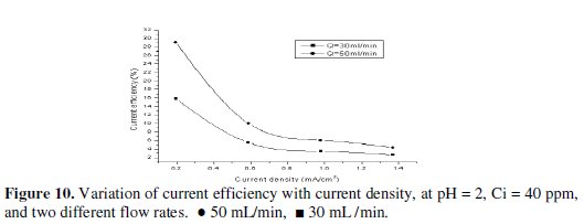
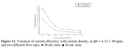
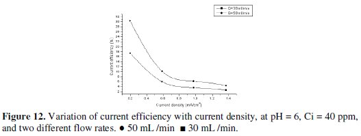
Based on the above discussed results, it can be concluded that the optimum operating conditions were the flow rate (100 mL/min), pH of inlet solution equal (6), and initial concentration of lead (40 mg/L). Recovery of lead During the deposition process, the current distribution over the bed is not uniform. Therefore, it is expected that most of the lead is depositing on the lower part of the bed. However, during the reversal of the polarity and the use of a rod of lead as cathode, we can recover the lead in pure state. This also can be achieved by burning the graphite which contains lead at 400 °C, which is enough to completely oxidize the graphite. Table 3 shows that the optimum current density for lead recovery.

From these results, the optimum current density for lead recovery is 1.27 mA/cm2.
Table 4 shows that the weight of lead is decreased after recovery.

This can be explained as during the reversal of the polarity, little amount of lead is leached at first, followed by increasing leaching rate of lead as dissolution process that took place over entire bed.
Conclusions
This study generated important information on the optimal conditions of several variables that influence the electrochemical cell incorporating flow-by porous graphite electrodes. The maximum removal efficiency and current efficiency were obtained at a flow rate of 100 mL/min, for initial concentration 40 mg/L, with a current density of 0.195 mA/cm2, 97.75% and 60.7%, respectively, with a residual concentration of 0.9 mg/L. Removal efficiency slightly decreases with the decrease in pH. This is due to the fact that, at lower pH, the main reaction is hydrogen evolution which accumulates on the cathode bed surface and therefore interferes with the deposition of lead.
References
1. Bahadir T, Bakan G, Altas L, et al. Enzyme and Microbial Tech. 2007;41:98. [ Links ]
2. Mahvi A H, Naghipour D, Vaezi F, et al. Am J Appl Sci. 2008;2:372. [ Links ]
3. Murugesan G S, Sathishkumar M, Swaminathan K. Bioresour Tech. 2006;97:483. [ Links ]
4. Ahmedna M, Marshall W E, Husseiny A A, et al. Water Res. 2014;38:1062. [ Links ]
5. Kobya M, Demirbas E, Senturk E, et al. Bioresour Tech. 2005;96:1518. [ Links ]
6. Anderson J R, Weiss C O. Method for precipitation of heavy metal sulphides. Patent, USA; 1973. [ Links ]
7. Smara A, Delimi R, Chainet E, et al. Sep Purif Tech. 2007;57:103. [ Links ]
8. Metcalf I, Eddy. Wastewater Engineering Treatment and Reuse. 4th ed. New York:McGraw Hill,;2003. [ Links ]
9. Nogami M, Ismail I M, Yamaguchi M, et al. J Solid State Chem. 2003;171:353. [ Links ]
10. Ismail I M, Nogami M, Suzuki K. Trans Egyptian Soc Chem Eng. 2004;30:383. [ Links ]
11. Abd El-Rahman K M, El-Sourougy M R, Abdel-Monem N M, et al. J Nuclear Radiochem Sci. 2006;7:21. [ Links ]
12. Ismail I M, El-Sourougy M R, Abdel Moneim N, et al. Solvent Extr Ion Exch 2002;20:589. [ Links ]
13. Ismail I M, El-Sourougy M R, Abdel Moneim N, et al. J Radioanal Nucl Chem 1999;240:59. [ Links ]
14. Ismail I M, El-Sourougy M R, Abdel Moneim N, et al. J Radioanal Nucl Chem 1998;237:97. [ Links ]
15. Ismail I M, Nogami M, Suzuki K. Solvent Extr Ion Exch 2003;21:465. [ Links ]
16. Ismail I M, Nogami M, Suzuki K. Sep Purif Technol. 2003;31:231. [ Links ]
17. Ismail I M, El-Sourougy M R, Abdel Moneim N, et al. Separation of Caesium and Cobalt from Contaminated Waste Water Using Potassium Nickel Hexacyanoferrate Complex. Proceedings of the International Symposium on Future Issues of Research on Science and TechnologyFirst`97. Tokyo, Japan;1997 [ Links ]
18. Ismail M, Soliman A, Abdel-Monem N, et al. Nickel Removal from Electroplating Waste Water Using Stand alone and Electrically-Assisted Ion Exchange Process. Int J Env Sci Tech. Accepted for publication.
19. Peters W R, White E T, Carole Y K, et al. J Water Pollut Control Fed 1986;58:481. [ Links ]
20. Sadrzadeh M, Mohammadi T, Ivakpour J, et al. Chem Eng J. 2008;144:431. [ Links ]
21. Patterson J. Industrial Wastewater Treatment Technology. 2nd ed. Boston:Butterworth Publisher;1985. [ Links ]
22. Kazemipour M, Ansari M, Tajrobehkar Sh, et al. J Hazard Mater. 2008;150:322-327. [ Links ]
23. Mishraa P C, Patel R K. J Hazard Mater. 2009;168:319-325 [ Links ]
24. Alizadeh T, Amjadi S. J Hazard Mater. 2011;190:451. [ Links ]
25. Liua Y, Liub Z, Gaoa J, et al. J Hazard Mater. 2011;186:197. [ Links ]
26. Khajeha M, Heidarib Z S, Sanchoolia E. Chem Eng J. 2011;166:1158. [ Links ]
27. Esalah J, Husein M M. Sep Sci Technol. 2008;43:3461. [ Links ]
28. Winfield B A. Water Res. 1979;13:561. [ Links ]
29. Ismail I M, Abdel-Salam O E, Ahmed T S, et al. Port Electrochim Acta. 2013; 31:207. [ Links ]
30. Gonzalez-Garcia J, Bonete P, Exposito E, et al. J Mater Chem. 1999;9:419. [ Links ]
31. Saleh M M. J Phys Chem B. 2004;108:13419. [ Links ]
32. Joseph B, Arthur S, Kushner. Water and Waste Control for the Plating Shop. 3rd ed. Cincinnati, Ohio: Gardner Publications Inc;1997.
33. Alkire R, Ng P K. J Electrochem Soc. 1974;121:95. [ Links ]
34. Alkire R, Ng P K. J Electrochem Soc. 1977;124:1220. [ Links ]
35. Daewon P, Dowon Ch, Jeh B J. Water Res. 2011;35:57. [ Links ]
36. EL-Deab M S, Saleh M M, EL-Anadouli B E, et al. J Electrochem Soc. 1999;146:208. [ Links ]
37. Ponce de Leon C, Pletcher D. Electrochim Acta. 1996;41:533. [ Links ]
38. Sarfarazi F, Ghoroghchian J. Microchem J. 1994;33:43. [ Links ]
*Corresponding author. E-mail address: dr_ismail@icem-group.org
Received 24 February 2014; accepted 27 February 2014


