


Serviços Personalizados
Journal
Artigo
 Inglês (pdf)
 Artigo em XML
 Referências do artigo
 Enviar este artigo por email
Indicadores
-
 Citado por SciELO
 -
 Acessos
Links relacionados
-
 Similares em
SciELO
Similares em
SciELO
Compartilhar

 Permalink
Ciência & Tecnologia dos Materiais
versão impressa ISSN 0870-8312
C.Tecn. Mat. v.22 n.3-4 Lisboa jul. 2010
Strength of aluminium resistance spot welded and weldbonded joints
A.M. Pereira(1)*, J.A.M. Ferreira(2), F.V. Antunes(2) and P.J. Bártolo(1)
(1) CDRsp, Centre for Rapid and Sustainable Product Development, Polytechnic Institute of Leiria, Morro do Lena - Alto Vieiro, 2400-901 Leiria, Portugal.
(2) CEMUC, Mechanical Engineering Department, University of Coimbra, Rua Luís Reis Santos, Pinhal de Marrocos, 3030-788 Coimbra, Portugal.
ABSTRACT
The increasing restrictions in terms of safety and energy consumptions imposed in the transport vehicles construction promotes the use of new materials and new processes searching weight reduction. Lighter materials and better joining processes, like adhesive bonding can contribute to obtain some weight gain. Present work studies the shear strength obtained with weldbonding technique and compares it with the traditional resistance spot welding. The single lap joints were obtained with thin plates of 6082–T6 alloy and a high strength epoxy adhesive of two components (araldite 420 A/B). The strength of weldbonded joints was found to be significantly higher than equivalent spot welded joints. Numerical models were developed replicating experimental work. Nugget diameter was found to have a major influence in stiffness and stress level, while thickness reduction showed a much lower influence. The adhesive reduced significantly the stress level at the nugget root.
Keywords: Resistance spot welds, weldbonding, mechanical properties, finite element analysis.
RESUMO
As crescentes restrições em termos de segurança e consumo de energia impostas na construção de veículos de transporte promove o uso de novos materiais e processos procurando reduzir o peso. Materiais mais leves e melhores processos de ligação, como as ligações adesivas, podem contribuir para obter algum ganho no peso. O presente trabalho estuda a resistência ao corte em juntas soldo-coladas e compara com a tradicional soldadura de resistência por pontos. As juntas de sobreposição simples foram obtidas com placas finas de liga 6082-T6 e um adesivo epóxido de alta resistência de dois componentes (Araldite 420 A/B). A resistência das juntas soldo-coladas é significativamente mais elevada do que das juntas soldadas por resistência por pontos. Foram desenvolvidos modelos numéricos para reproduzir o trabalho experimental. Verificou-se que o diâmetro do ponto de soldadura tem uma grande influência na rigidez e resistência, enquanto que a indentação do eléctrodo tem uma influência muito menor. O adesivo reduziu significativamente o nível de tensão na raiz do ponto de soldadura.
Palavras chave: Soldadura de resistência por ponto, Soldo-colagem, propriedades mecânicas, análise por elementos finitos.
1. Introduction
The increasing restrictions in terms of performance, safety and energy consumptions imposed in the transport vehicles construction promotes the use of new materials and new processes searching weight reduction. Lighter materials, like aluminium alloys and better joining processes, like adhesive bonding and spot welding can contribute to obtain some weight gain [1,2]. Present work analysis the expected benefits on shear strength obtained by using weldbonding technique instead of the traditional resistance spot welding (RSW) or adhesive bonding in aluminium based thin plates.
Weldbonding is an alternative technology for joining parts consisting of structural adhesives and spot-welding. This hybrid process of joining is used to maximize the benefits of both joining processes [3]. The weldbonding offers advantages relatively to the other conventional joining processes, namely, acoustic isolation, vibration attenuation, reduction of corrosion, and more uniform stress distribution. Chang et al. [4], Ghosh and Vivek [5] and Santos et al. [6] conducted studies to characterize and compare the performance of resistance spot welding, adhesive bonding and weldbonding joining processes under static loading. Several experimental studies have been reported on the mechanical behaviour of welbonding joints, particularly in steel adherends. Joints with aluminium adherends are however less studied. Static behaviour needs a significant research effort in order to understand the failure mechanisms and the influence of joining parameters like surface pre-treatment, adhesive thickness, adherends thickness or process parameters (weld current, weld time and electrode force) of spot welded joints.
Strength of weldbonded joints, adhesi-bonded and resistance spot-welded was predicted by Samhan et al [7]. This study demonstrated that, the major principal stress predicted in spot-welded joints is small, when compared with those associated with weldbonded and adhesive bonded joints. In weldbonded joints the stresses are concentrated at the overlap region as well as both ends of the welding nugget. This work also demonstrated the effective role played by the adhesive layer in strengthening weldbonded joints. Chang et al. [4] compared stress distributions of weldbonded joints, spot welded joints and adhesive bonded joint. The numerical results showed that the stresses in the lap zone of weldbonded joints are more uniformly distributed than in spot-welded joints. The stresses of weldbonded joints in the lap zones, with the exception of the spot weld zones, have almost the same characteristics as those of adhesive bonded joints. The strengths of these joints predicted from the results of the stress analysis are coincident with existing experimental results. The application of adhesives in spot welding also improves the joint fatigue performance, while the presence of weld spots in adhesive-bonding has a negative effect on the joint fatigue performance [3].
Although the effect of the process parameters in the mechanical behaviour of weldbonded carbon and stainless steels is well documented, results for aluminium alloys still are scarce. A better understanding of the effect of process parameters on the mechanical behaviour of weldbonded joints in heat treatable aluminium alloys such as 6082-T6 is required. The objective of the current research is to investigate the effect of process parameters on shear strength and failure mode of weldbonding joints made of thin sheets of 6082-T6 aluminium alloy.
2. Materials processing and testing
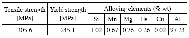
The material considered for the adherends in the current study was the 6082–T6 aluminium alloy in the form of 1.0 thick sheet. The nominal chemical composition, obtained from emission spectrometer analysis, and the basic mechanical properties of this alloy, obtained using tension static tests and the resonant technique [8], are given in Table 1. The single lap joints were obtained using a high strength epoxy adhesive (Araldite 420 A/B from Hunstman) and resistance spot welding (RSW). The mechanical properties of the adhesive were obtained from de Moura et al. [9].
Table 1. Chemical composition and mechanical properties of the 6082-T6 aluminium alloy.
The weldbonding joints were obtained using the same high strength epoxy adhesive (araldite 420 A/B); bonding was performed immediately before weld. The AA 6082-T6 sheets were cut to 100 x 25 mm2 and their sheet surfaces were randomly abraded with P220 grade sandpaper. At the end the surface was cleaned with dry air, to eliminate surface contamination and promote adhesion, before adhesive bonded. Surface roughness was measured after surface preparation, using a mechanical stylus contact method with a radius of 5 µm, and the average roughness is Rz =7.2 ± 0.70 [mm]. The bonding process was optimized in a previous work by Pereira et al. [2,10] and it was found that best adhesive properties are obtained the surface pre-treatment consisting of abrasive polishing. For adequate bonding, the specimens were compressed with a pressure of 0.157MPa applied during all cure time (4 h at 50 ºC).
The welds were done using a Sciaky RSW type PMC02 electric resistance spot welding machine, with a nominal welding power of 100 kVA. The machine employs type C18200 electrodes having an end diameter of 15.25 mm, an electrical conductivity of 0.463 m/Ωmm2 and a tensile strength of 310 N/mm2. The hemispherical electrode tip radius is of 101.6 mm. The welding conditions were selected based on previous tests [11]. Thirteen weld series were done, changing weld current, time and electrode force. The timing diagram used in all tests is schematically represented in Figure 1.

Fig. 1. Typical spot-welding cycle.
The parameters were: electrode force 2354 - 4709 N, weld time 1 - 5 cycles and weld current 23.5 - 28.7 kA. The squeeze and forge times were constant in all tests. The forge force used was 6474.6 N. The welds were done in open air at room temperature. Figure 2 shows the specimen geometry and dimensions of the specimens.
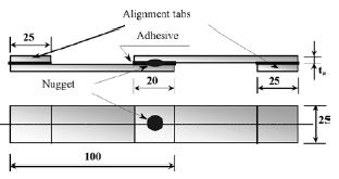
Fig. 2. Dimensions of RSW and weldbonded specimens (not to scale, dimensions in mm).
Five specimens were welded in each series; four specimens to be used for static tensile shear strength testing and one for microstructure examination and hardness measurement. Specimens used for microstructure examination and hardness measurement were cut out along the center of the nugget, at right angles to the longitudinal direction of specimens. Specimens were polished and a modified Poultons reagent was employed to reveal the microstructure. Metallographic analysis was performed using a ZEISS HD 100 optical microscope. Hardness measurements were carried out in two directions (along the radius of the nugget and through the sheet thickness) using a Struers Duramin Vickers machine, under a load of 100 g. Finally, the shear strength testing was done in an electromechanical Instron Universal Testing machine at a constant cross-head speed of 1 mm/min, up to the final failure of the joint.
3. Results and discussion
3.1. Experimental results
Figure 3 shows typical load – extension curves obtained for RSW and weldbonding joints. It is evident that weldbonded joints have much higher failure loads and extension at failure than similar spot weld joints.
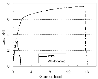
Fig. 3. Load – extension curves for RSW and weldbonded joints (with 6.5 mm diameter nuggets).
Figures 4 and 5 show the failure load versus the electrode force and weld current, respectively. For comparison the results for resistance spot weld (RSW) joints and weldbonded joints were superimposed. Both figures show that weldbonded joints have much higher strength than equivalent spot welded joints. On the other hand, the sensibility of weldbonded joints relatively to weld current and electrode force is negligible within the parameter range studied. These two findings mean that the resistance of the joint is controlled by the bonded liaison.
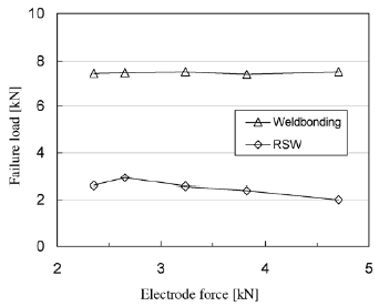
Fig. 4. Load failure against the electrode force. RSW parameters: weld time, 2 cycles; weld current, 26.9 kA.
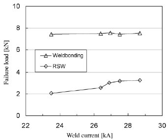
Fig. 5. Load failure against the weld current. RSW parameters: weld time, 2 cycles; electrode force, 3237 N.
In the tensile-shear testing of RSW and weldbonding joints two failure modes were obtained: pull out mode and interfacial mode. Figure 6 shows a typical pull out failure surface. Similar failure surfaces were obtained for both type of joints (RSW and weldbonding).
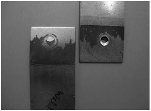
Fig. 6. Typical pull out weldbonding failure.
3.2. Numerical analysis
A numerical analysis was developed to understand the deformation and failure mechanisms of resistance spot welding and weldbonded joints. Sources of complexity are thickness reduction (i.e. the plastic deformation caused by the welding process), the small crack tip radius, the heterogeneity of the materials and the residual stresses. The material properties of spot-welded joints can vary widely between the base metal, the heat-affected zone, and the weld nugget itself. Figure 7 illustrates the model assumed. Only half specimen was studied, considering adequate symmetry conditions. The left side was fixed, replicating the upper grip of the servo-hydraulic testing machine. The rotation of the right side was inhibited, while the load was applied.
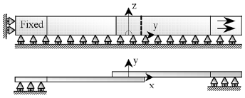
Fig. 7. Physical model.
The diameter of the nugget depends of electrode force, weld time and particularly of welding current. Values in the range 5-6mm were typically obtained. In previous works of Pereira et al [11] the static failure load versus nugget diameter was studied for RSW in aluminium. This diameter was found to be the geometrical controlling parameter, and a linear relation was obtained with failure load. The thickness reduction of adherends is also visible in Figure 8. The depth depends mainly on welding time and welding current, and values up to 15% of initial sheet thickness were obtained. Figure 8 shows that at the root of the nugget, the sheets are close, which indicates that the concordance radius is quite small. A radius of 5 mm was assumed in the numerical model. At relatively large distances from the nugget, the sheets are clearly separated, and a value of 80 mm was assumed. This is also the thickness of the adhesive in the weldbonded joints. The cracks start and propagate between de nugget and heat-affected zone (HAZ). Therefore it may be expected that maximum von Mises stress occurs at the edges of the nugget.
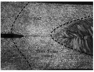
Fig. 8. Geometry at the root of nugget.
Both the aluminium alloy and the adhesive were modelled as having elastic-plastic properties. The elastic properties assumed were E=69070 MPa, υ=0.35 for the 6082-T6 aluminium alloy (obtained experimentally using the resonant technique), and E=1850 MPa, υ=0.3 for the adhesive. The plastic behaviour was characterised with classical tension tests. The HAZ, (Figure 8) was identified with hardness measurements, as illustrated in Figure 9. A gray ribbon represents the hardness of the base material. A significant decrease in hardness was observed in the nugget of all the welds shown, resulting from precipitates dissolution. The evaluation of the shear strength of the nugget and HAZ of spot welds is difficult, because those regions are narrow and present microstructural gradients. Currently, the yield and tensile strength of materials are related to their hardness through empiric equations characterised by the generic equation (1), where HV and s represent the Vickers hardness and tensile strength of the material, respectively, and K is approximately constant, assuming the elastic properties are approximately constant inside each family of materials [12,13]. In addition, according to the Tresca criterion, both the shear and tensile strength of a metal are connected by a mathematical constant (shear strength is half of the tensile strength of the material).

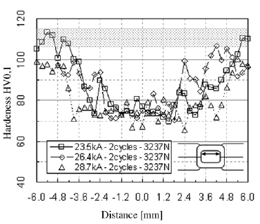
Fig. 9. Hardness plot.
Figure 10 shows the finite element mesh, which is composed of 82552 linear isoparametric elements and 90204 nodes. Characteristics aspects of this model are the small radius considered at nugget root (5 µm), the thickness of the adhesive (80 µm) and the possible consideration of four distinct materials (base material, nugget, HAZ and adhesive). Notice also that there is a region around the nugget without adhesive. This model is relatively heavy, therefore a second model (called model 2) was proposed for parametric studies concerning geometric, load and material parameters. In this model a sharp notch was assumed at nugget root. Figure 11 compares experimental results with numerical predictions. An acceptable agreement is evident for relatively low loads. The experimental results lie between model 1 and 2. Notice that the thickness is different in models 1 and 2, because a gap of 80 µm was considered in model 1 between the sheets. The numerical model is not predicting failure, which explains the difference for relatively high loads.
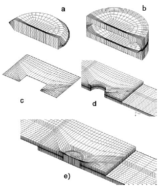
Fig. 10. Finite element mesh (model 1). a) Nugget. b) Heat-affected zone; c) Adhesive; d) Base material; e) Global view.
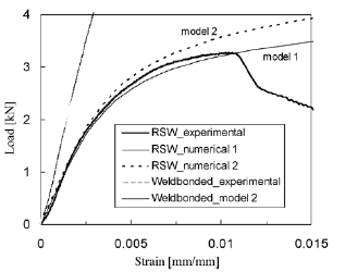
Fig. 11. Numerical versus experimental results (Nugget diameter: D = 5.7 mm).
Figure 12 shows the influence of nugget diameter (D) on global stiffness. For relatively low loads, D does not influence the global deformation of the joint. When the plastic deformation initiates (P>2000 N), the specimen with lower nugget diameter shows a quite reduced stiffness. Figure 13 shows the influence of nugget diameter (D) and thickness reduction (EI) on plastic strain (&epsilonp). The distance from nugget root (d) is indicated. The indentation has a minor influence, but diameter reduction increases significantly the stress and strain levels. Figure 14 shows the equivalent von Mises stress (σVM), measured from the root of the notch. The stress level is significantly higher for the RSW joint, which explains its lower resistance. In other words, the adhesive has a protective effect in the spot weld.
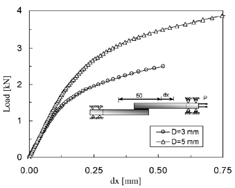
Fig. 12. Influence of nugget diameter on global stiffness (P = 2.5 kN).
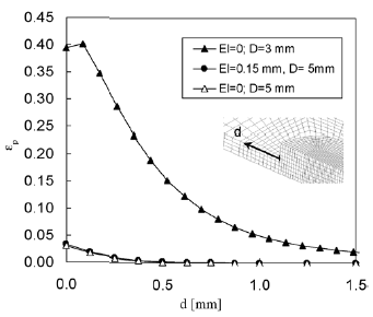
Fig. 13. Influence of nugget diameter and thickness reduction on equivalent plastic strain (P=2.5 kN).
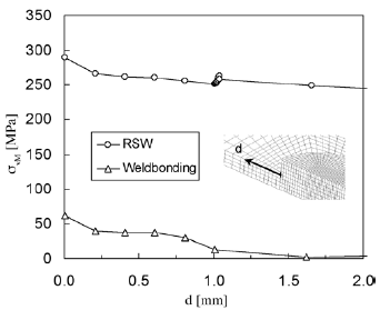
Fig. 14. Influence of process joining on equivalent von Mises stress (P=2.5 kN).
Sensitivity analysis
A sensitivity analysis was developed to understand the influence of the different parameters on the stress and strain field, and therefore on joints strength. There are a huge number of physical parameters, namely geometric parameters (nugget diameter, crack tip radius, nugget position, thickness and length of adherends, thickness reduction) and material parameters (elastic-plastic properties). In order to compare these different parameters, non-dimensional sensitivity was considered, defined by equation (2) [14]:
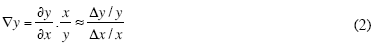
being x one of the independent physical parameters and y the dependent parameter. Notice that sensitivity  y=0.5i indicates that a variation of 1% in x produces a variation of 0.5% in y. The dependent parameter considered was the equivalent plastic strain near the crack tip region. The base parameters for which the sensitivity analysis was developed were: nugget diameter of 5.75 mm; radius of 5 µm at the crack tip, adherends with thickness of 1 mm and length of 100 mm, overlap length of 20 mm, thickness reduction of 0.1 mm, homogeneous aluminium alloy, no adhesive and tensile load of 3000 N. The 2D finite element model was considered in this analysis, in order to reduce the numerical effort involved in model preparation and computation time.
Figure 15a shows the influence of different geometric and material parameters (D – Spot diameter, ρ – Radius at spots root, EI – Thickness reduction; L, ta – Length and thickness of adherends; SP – Spot position, E – Youngs modulus; YS – Yield stress) on the equivalent plastic strain at spots root. There is a great influence of adherends thickness (ta), yield stress (YS) and notch radius (ρ). The equivalent von Mises stress, in figure 15b, has relatively low variations compared with plastic strain (notice the different scales). For relatively high stress level, as is the case in the notch region, small variations of stress produce relatively large strain variations. Once again yield stress and adherends thickness are the most relevant parameters. Figure 15c presents the influence on displacement measured at a distance of 50 mm. The spot diameter (D), the length and thickness of adherends, and the yield stress have relatively high influences. Finally, figure 15d shows the influence of an adhesive on stress level (weldbonded joint). There is a dramatic decrease of stress level, which eliminates the local plastic deformation at spots root and explains the huge increase in joints strength.
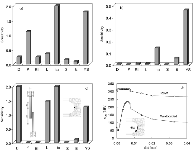
Fig. 15. a) b) c) Non dimensional sensitivity of plastic strain, von Mises stress and global compliance, respectively, relatively to geometrical and material parameters; d) Resistance spot welding versus welbonding.
4. CONCLUSIONS
The influence of the weld parameters on the tensile shear strength of aluminium alloy 6082-T6 resistance spot welded and weldbonded joints was studied. Numerical models were developed to predict global stiffness and local stresses. The conclusions obtained are summarised as follows:
- Weldbonded joints have much higher strength than similar spot welded joints;
- Sensitivity of weldbonded joints relatively to weld current and electrode force is negligible within the parameter range studied;
- Strength of the weldbonding joint is controlled by the bonded liaison;
- A good agreement was found between numerical predictions of load versus displacement curves and experimental results;
- Nugget diameter was found to have a major influence while thickness reduction has a residual effect;
- The stress level at nugget root was found to reduce significantly by adding the adhesive.
AKNOWLEDGEMENTS
The authors thank the financial support of the Portuguese Foundation for Science and Technology (Grant SFRH/ BD/37384/2007) and the assistance of the company OGMA – Indústria Aeronáutica de Portugal in the execution of the welds.
REFERENCES
[1] T.A. Barnes, I.R. Pashby, Joining techniques for aluminium spaceframes used in automobiles Part II – adhesive bonding and mechanical fasteners, Journal of Materials Processing Technology, 99 (2000) 72-79. [ Links ]
[2] A.M. Pereira, J.M. Ferreira, F.V. Antunes, P.J. Bártolo, Study on the Fatigue Strength of AA 6082 – T6 Adhesive Lap Joints, Int. J. Adhes. Adhes, 29 (2009) 633- 638.
[3] B. Chang, Y. Shi, L. Lu, Studies on the stress distribution and fatigue behavior of weld-bonded lap shear joints, Journal of Materials Processing Technology, 108 (2001) 307-313.
[4] B. Chang, Y. Shi, S. Dong Comparative studies on stresses in weld-bonded, spot-weldedand adhesivebonded joints, J Mater Process Technol, 87 (1999) 230-236.
[5] P.K. Ghosh, Vivek, Weldbonding of stainless steel, ISIJ International, 43 (1) (2003) 85-94.
[6] I. O. Santos, W. Zang, V.M. Gonçalves, N. Bay, P.A.F. Martins, Weld bonding of stainless steel, Inter J Machine Tools Manufacture, 44 (2004) 1431-1439.
[7] A. Al-Samhann, S.M.H. Darwish, Strength prediction of weld-bonded joints, International Journal of Adhesion & Adhesives, 23 (2003) 23-28.
[8] F.V. Antunes, A. Ramalho, J.A.M Ferreira, C. Capela, P. Reis,Determination of Elastic Properties by Resonant Technique: a Sensitivity Analysis, J. Testing and Evaluation, 36(1) (2008) 89-99.
[9] M.F.S.F. de Moura, R. Daniaud, A.G. Magalhães, Simulation of mechanical behaviour of composite bonded joints containing strip defects, Int. J. Adhes. Adhes., 26 (2006) 464-473.
[10] A.M. Pereira, P.J. Bártolo, J.M. Ferreira, F.V. Antunes, Laminated object manufacturing with aluminium bonded sheets. In Bártolo, P.J. et al (Eds), Virtual and Rapid Manufacturing-Advanced Research in Virtual and Rapid Prototyping, Taylor and Francis, London, 597-601, 2008.
[11] A.M. Pereira, J.M. Ferreira, A. Loureiro, J.D.M. Costa, P.J. Bártolo, Effect of Process Parameters on the Strength of Resistance Spot Welds in 6082-T6 Aluminium Alloy, Materials and Design 31 (2010) 2454–2463.
[12] M.A. Salazar-Guapuriche, Y.Y. Zhao, A. Pitman, A. Greene,Correlation of Strength with Hardness and Electrical Conductivity for Aluminium Alloy 7010, Materials Science Forum, 519-521 (2006) 853-858.
[13] R. Wanga, G. Shang, Low-cycle fatigue life prediction of spot welds based on hardness distribution and finite element analysis, International Journal of Fatigue 31 (2009) 508-514.
[14] D. Tortorelli and P. Michaleris, Design sensitivity analysis: overview and review, Inverse problems in Engineering 1, (1994) 71-105.
