


Serviços Personalizados
Journal
Artigo
 Inglês (pdf)
 Artigo em XML
 Referências do artigo
 Enviar este artigo por email
Indicadores
-
 Citado por SciELO
 -
 Acessos
Links relacionados
-
 Similares em
SciELO
Similares em
SciELO
Compartilhar

 Permalink
Ciência & Tecnologia dos Materiais
versão impressa ISSN 0870-8312
C.Tecn. Mat. v.22 n.3-4 Lisboa jul. 2010
Utilization of Durability Criterion to Develop Automotive Components
Luiz Carlos H. Ricardo
Assistant Professor in Structural Mechanics Division of Structural Mechanics Department of Civil Engineering Aalborg University Sohngårdsholmsvej 57, Aalborg, Denmark, 9000
ABSTRACT
Today the automotive companies must reduce the time to development of new products with improvement in performance, durability and low cost reductions where possible. To achieve this goal the carmakers need to improve the design criterion of car systems like body, chassis and suspension components. This paper will present a review of the techniques used in the automotive industry regarding durability before mentioned systems. The paper will present the procedures to obtain the spectrum loading to use in finite element analysis and the validation in laboratory and proving grounds.
Keywords: design criterion, durability, proving ground, finite element method
RESUMO
A indústria automóvel tem de reduzir o tempo para desenvolvimento de novos produtos, e simultaneamente assegurar melhorias no desempenho, durabilidade e quando possível reduções de custos. Estes objectivos exigem melhorias nos critérios e procedimentos de projecto de sistemas como a carroçaria, o chassis e a suspensão. O presente artigo apresenta uma revisão de técnicas usadas na indústria automóvel no tocante à durabilidade dos sistemas mencionados anteriormente. O artigo apresenta procedimentos para obter o espectro de carga para uso nos modelos de elementos finitos e validações em laboratório e ensaios em pista.
Palavras chave: critério de projecto, durabilidade, pista de ensaios, método dos elementos finitos.
1. Introduction
The heart of the design process is the set of analysis tools that the designer employs. The use of the finite element analysis is shown in Figure 1.Scale model testing using simulated service loads should normally be considered in the early stages of the design process [1].The engineering procedures used in the automotive industry to promote structural integrity in cars and trucks are continuously evolving. Significant changes are still taking place in instrumentation, analysis procedures and methods of handling and analyzing data. As long as these techniques continue to evolve, engineers will have the opportunity to utilize these new resources to make improvements in their fatigue design procedures. To plan a product, the engineering department may need to have a survey completed to determine the needs of the customer. In each area it is possible to determine the range of expected usage. The usage pattern of many products primarily results from, the different applications of the product as well as the customer who is using it.
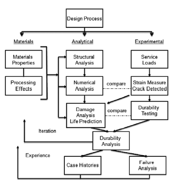
Fig. 1 - Design Process
2. Durability Procedures
Carboni et. al [2] present a methodology to the development of truck wheels where these components are given special attention, because the fatigue design criterion must guarantee an appropriate structural integrity during service life. In fatigue assessment of wheels, the commonly accepted procedure by manufacturers is to pass two durability tests, namely the radial fatigue test and the cornering fatigue test [3–4]. These tests are conventionally defined and are based on simple load conditions not representing the real in-service behavior of components.
Another widely used type of test is based on standardised load spectra (grouped under the name CARLOS: CAR LOading Spectra) consisting of a preset sequence of lateral and vertical forces obtained by extrapolation of loads measured directly on components during typical (straight driving, braking, cornering, parking,..) both on-road and off-road. In the special case of truck wheels, LBF (Germany) has developed Eurocycle [5,6], an accelerated test spectrum able to represent, in a 65 km route, 2032 km of typical exercise of truck wheels on European roads. Load spectra are applied to the real component, during fatigue tests, by a special Biaxial Test Facility [6,7].
The manner in which a product interacts with the environment during its use produces forces on hence it is necessary to characterize their magnitude, frequency, rate of change, etc.
To evaluate the durability of a product for any specific configuration, usage area and type customer, and the designer must obtain and evaluate loading information by numerical and experimental techniques (Ricardo & Andrade [8]. In service, the vehicle components are in most cases subjected to variable loads. The structure represents more or less complicated elastic systems; time-varying operational loads can excite their natural modes. Therefore, the response, which is in the form of a stress-time history at a point of the structure that is far enough from the point of load introduction, may show differences with regard to amplitudes as well as to frequencies compared with the corresponding load-time history. This means that a stress-time history contains both the effects of external loadings and the response of the structure to these loadings. Grubisic [9] introduces a way to determine the load spectrum of design showing some procedures normally used in these situations. To determine the loadings that will be in used estimating life of automotive components some conditions are required:
1) measurements done with a vehicle prepared with sensors to run in mixed routes (off-road, city and both)
2) measurements done with a vehicle prepared with sensors to run by different drivers in the same routes
3) measurements done with a vehicle prepared with sensors uses by different drivers in different routes. Figure 2 shows the parameters used to specify the loading spectrum.
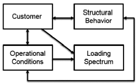
Fig 2 - Parameters of Loading Spectrum
The utilization of the Power Spectral Density (PSD) analysis are obtained from the acceleration signals as part of the test program; design a structure or component considering just static loads and knowing that service loads are dynamic is wrong, because the regular fatigue criteria like Goodman [10] and Gerber [11] are based on the static loads and do not consider the effects of damage from natural frequencies in the structure. Knowledge of natural frequencies is an important information on the dynamic behavior of the structure since it lets the experimental team to know if the assumptions used in the design are correct or not.
In the literature there are some works that cover this subject; Morril et al. [12] introduce a methodology to work with random vibration in an automotive structure. Lin et al. [13] present a method performance estimation to be used during the experimental development. This method is based on a response frequency analysis, where the number of natural frequencies obtained is limited to provide the input to compute damage in each natural frequency, by applying the Miner method [14].
Ricardo [15] presents an example of development of an automotive component considering finite element method, variable amplitude loading and Miner method.In this paper a battery tray of a car is shown; that is instrumented with accelerometers as shown in Figure 3 (channels 1 to 6) with current battery tray and support; and the strain gages in Figure 4 (channels 7 to 11) shown the proposal of battery tray in hard points to input the data in the battery tray CAE model to check the structural behavior. The acquisition data were in several roads tests that meaning the major service loads and the frequencies of work were obtained. The frequencies of work are compared with numerical frequencies obtained from the CAE model in a modal analysis. Some measurements are shown in Figures 5 and 6. The validation of best proposal will be in a proving ground with accelerated durability test during 12,000 Km.
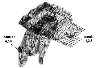
Fig. 3 - Position of Accelerometers
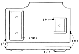
Fig 4 - Position of Strain-Gages
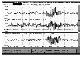
Fig 5 - Acceleration at Battery Tray
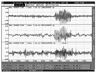
Fig. 6 - Strain at Battery Support
Figure 7 gives transformations from acceleration into the frequency domain. The frequencies from channel 1 of 9 Hz (x), and channel 2 of 18 Hz (y), will be used to compare with modal analysis results, obtained by application of Fast Fourier Transform (FFT) of the acceleration versus time signal. The lower level peaks, as in channel 1 of 19 Hz and in channel 2 of 28 Hz, are not important, as they were found to have low amplification in the component during tests on the proving ground, and so do not cause significant fatigue damage in either the current design or a proposed modification. In general, high peaks on these plots that correspond to natural frequencies in the component need to be avoided to preclude resonance problems that cause large amplitude vibrations.
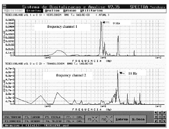
Fig. 7 - Experimental data of acceleration in the frequency domain, specifically for channel 1 and channel 2. Energy content in square of gravity units (g2)/ Hz is plotted versus frequency (Hz).
Table 1 gives the natural frequencies for the component obtained from the FEM model in a modal analysis. This information makes it possible to identify input frequencies that would not be a concern in terms of resonance problems. The field data frequencies are also compared to the frequencies obtained from numerical analysis.
Table 1 - Numerical Values of Natural Frequencies from Modal Analysis
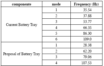
Table 2 shows the results, the damage accumulative analysis, and their correlation with the durability criterion and Figure 8 gives an example of damage matrix utilized to estimate the life of structure.
Table 2 - Results of damage accumulation
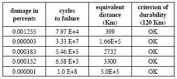
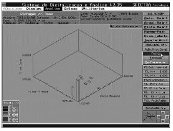
Fig 8 - Damage Matrix
Khalil & Topper [16] present a paper that cover the crack propagation in steels with application in automotive area. The paper determines the crack opening stress intensity factors in a aluminum alloy 2024-T351 and a SAE 1045 under variable amplitude loadings.
The average crack-opening stresses were within between 6 and 13 percent of the average calculated crack-opening stresses. The fatigue life predictions based on the modeled crack-opening stresses and the fatigue notch model were in good agreement with the experimentally determined fatigue data. In the interest of simplifying the use of crack-opening stress in design, the average crack-opening stress was correlated with the frequency of occurrence of the cycle reducing the crack-opening stress to the average level.
The use of a crack-opening stress level corresponding to the cycle causing a reduction to a crack-opening stress reached once per 200 cycles gave a conservative estimate of fatigue life for the soft metals 2024-T351 aluminum alloy and 1045 annealed steel, while for the 1045 quenched and tempered steel the cycle causing a reduction to a crack-opening stress reaching once per 10 cycles gave a conservative life estimate.
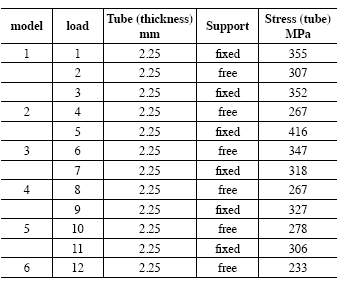
In Ricardo [17], it is presented weld seam simulations in additional suspension components are presented. Specifically, several types of weld seams in shock absorbers structures are modeled. HYPERMESH [18] and ABAQUS [19] are used as pre-postprocessor and solver, respectively, to perform the numerical modeling. Figure 9 show a case example and a detail thereof. The design criterion used in the FE models is fatigue failure or stresses exceeding 70% of the yield strength under bending about any axis. Physical tests were conducted to validate the numerical results, and close correlation between the numerical and experimental data was found. Both manufacturing and stress level considerations were examined, and the best option of weld seam detail was selected. To reproduce the weld seam configuration with a high level of confidence, some parts that might normally be modeled with shell elements were instead modeled with solids elements, specifically, ABAQUS type C3D10, seen in Figure 10 with present an example of post-processor of the analysis. Table 3 presents performance of some models.
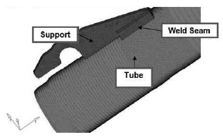
Fig. 9 - Example weld seam FE model.
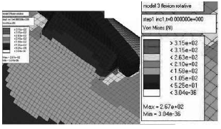
Fig. 10 - Model 3 of weld seam.
Table 3 - Summary of Results
3. Conclusions
The present paper shows some procedures to developing components in automotive applications considering durability criteria. The customers are requesting products with more confidence level regarding structural integrity, low cost and high performance. The car will be continue to be a very useful way of transportation very useful and the trucks will continue to transport the products for long and short distances. These issues become the Research Engineering area to develop new design criteria and change the current one.
4. References
[1] SAE, Fatigue Design Handbook, USA,1988
[2] Carbonia, M.; Berettaa, S. & A. Finzi, Defects and in-service fatigue life of truck wheels, Engineering Failure Analysis, 10, 2003,pp. 45–57 [ Links ]
[3] ISO 3006 Road vehiclespassenger car wheelsfatigue testing methods, vol. 2. Switzerland, 1976
[4] Wright DH. Testing automotive materials and components. SAE Publication; 1993
[5] Grubisic V, Fischer G. Procedure for optimal lightweight design and durability testing of wheels. Int. J Vehicle Design, 1984
[6] Grubisic V, Fischer G. Automotive wheels, methods and procedure optimal design and testing. SAE Technical Paper 830135,1983
[7] Grubisic V, Fischer G, Heinritz M. Design optimisation of forged wheel hubs for commercial vehicles. SAE Technical Paper 841706, 1984
[8] Ricardo, L. C. H. & Andrade, A.P.H.; The use of Fatigue to Design Structures Under Variable Loading, In : Miller, K.J.; Brown, M.W. & Rios, E.R. (Eds.). ECF12 Fracture from Defects, Emas Publishing, Sheffield, England, September, Vol. I: Fatigue, pp. 289-296; 1998
[9] Grubisic, V. Determination of Load Spectra for Design and Testing, Int. J. of Vehicle Design, Vol. 15, Nº1/2, UK, 1994
[10] Goodman, J. Mechanics Applied to Engineering, Longmans, Green & Co., London, England, 1899
[11] Gerber, W. Bestimmung der Zulossigen Spannungen in Eisen Constructionen, Z. Bayer Arch. Ing. Ver. , Vol.6, Alemanha, 1874
[12] Morril, J H. ; Achatz, T. & Khosrovaneh, A. An Application for Fatigue Damage Analysis Using Power Spectral Density from Road Durability Events, SAE Paper 980689, USA, 1998
[13] Lin, J.S.; John, C.M. St; and Luft, P. The Use of Frequency Domain Vibration Methods for Automotive Component Durability, SAE paper 960971, USA,1996
[14] Miner, M. A. Cumulative Damage in Fatigue, Journal. of Applied Mechanics, ASME, Vol.12, USA, 1945 p. A159-A164
[15] Ricardo L.C.H; Andrade, A. P. H. & Topper T.H. Experimental Procedure to Estimate the Fatigue Life of a Component under Variable Amplitude Loading, (2002) In: Blom, A.F (Ed.). Fatigue 2002, Emas Publishing, Stockholm, Sweden, Vol. 4, pp.2293-2300
[16] M. Khalil ,T.H. Topper Prediction and correlation of the average crack-opening stress with service load cycles, International Journal of Fatigue ,25,2003, pp. 661–670
[17] Ricardo, L.C.H.; Simulation of Weld Seam in Suspension Components, SAE Brazil Congress, 2007 SAE Paper 2007-01-2534, November 28-30, Sao Paulo, Brazil
[18] Altair, Hypermesh version 7.0,USA, 2005
[19] Abaqus version 6.1, USA, 2004
