


Services on Demand
Journal
Article
 English (pdf)
 Article in xml format
 Article references
 Send this article by e-mail
Indicators
-
 Cited by SciELO
 -
 Access statistics
Related links
-
 Similars in
SciELO
Similars in
SciELO
Share

 Permalink
Portugaliae Electrochimica Acta
Print version ISSN 0872-1904
Port. Electrochim. Acta vol.33 no.2 Coimbra Mar. 2015
https://doi.org/10.4152/pea.201502111
An Efficient Amperometric Sensor for Hydrogen Peroxide by Using a Carbon Paste Electrode Modified with Cobalt Impregnated Zeolite
Banafsheh Norouzi* , Majid Moradian and Ali Malekan
Department of Chemistry, Qaemshahr Branch, Islamic Azad University, Qaemshahr, Iran
Abstract
Cobalt impregnated zeolite-modified electrode was prepared by mixing cobalt-zeolite (Co-Z) and graphite powder with different percentages. Using the cyclic voltammetric technique, the electrochemical oxidation of hydrogen peroxide at such electrodes was investigated. Experiments on zeolite show that it is not electrochemically active towards hydrogen peroxide oxidation in NaOH solution. The presence of cobalt ions in the zeolite matrix, by soaking the electrode in an aqueous Co(NO3)2 solution, markedly enhances the electrocatalytic activity which was found to depend on the cobalt content. On the other hand, the presence of zeolite and/or Co metals in the catalyst is essential; however, the electro-catalytic activity depends on different percentages of Co-Z. Under the selected conditions, the anodic peak current was linearly dependent on the concentration of the hydrogen peroxide in the range 0.03-9 and 0.006-0.1 mM with CV and amperometric methods, respectively. The detection limits (S/N=3) were also estimated to be 17 and 2.5 μM.
Keywords: Cobalt, Electrocatalytic oxidation, Hydrogen peroxide, Modified electrode, Zeolite.
Introduction
Zeolites are crystalline microporous solids that provide molecular-sized cages and passageways for excellent steric control of reaction paths [1, 2]. The pore windows and cages or channel structures of zeolites result in physical exclusion or inclusion of molecules or ions according to their sizes relative to that of the pores. The primary building blocks of zeolites are SiO4 and AlO4 tetrahedra.
These can link in several ways, resulting in arrays producing three-dimensional anionic networks. The presence of aluminum in the framework introduces a negative charge that is balanced by extra framework cation as a redox active guest. The framework Si to Al ratio can be controlled in the zeolite synthesis [3, 4]. For catalytic purposes, modification of zeolites is, therefore, carried out with some metals. The pore geometry is considered as the main reason for the different activity of zeolite-based catalysts. Transition metal-containing zeolites were found to exhibit a high catalytic activity. Ni-containing zeolites [5], Agzeolites [6], Pd-zeolites [7], Ti-zeolites [8], Pt-and Pt-Ru-zeolites [9] have been used for catalytic purposes.
On the other hand, hydrogen peroxide plays a significant role in the chemical and pharmaceutical industries as an oxidizing, bleaching and sterilizing agent. Also, it forms the diagnostic response for several medical sensing devices such as blood glucose monitors [10]. At high concentrations, hydrogen peroxide causes irritation to the eyes and skin and affects human health [11]. Further, the detection of hydrogen peroxide is an important task in many biological, medical and clinical studies [12, 13]. Many spectroscopic methods such as fluorimetry [14, 15], fiber-optic device [16, 17], chemiluminescence [18-20], and various electrochemical [21-26] methods have been developed for detection of hydrogen peroxide. Among these methods, the amperometric sensors are especially promising because of their simplicity, high sensitivity and selectivity. Various chemically modified electrodes have been suggested for detection of hydrogen peroxide. Most of the modified electrodes for amperometric determination of hydrogen peroxide are based on enzymes such as horseradish peroxidase [27- 30]. However, there still exist some practical problems related to the use of enzyme in these analytical devices, due to the short operational lifetimes and low reusability of these biocatalysts [31, 32]. However, the employment of non- enzymatic sensors for determination of hydrogen peroxide is an important priority in chemical, food and environmental.
Several methods have been used for incorporation of zeolite particles into electrodes. These include the use of a polymer layer containing zeolite [33, 34], pressed zeolite pellets [35], carbon-paste mixed with zeolite particles [36, 37], zeolite-carbon composites [38], and co-deposition of zeolite with organic salts [39]. For analytical applications, it is highly desirable to develop robust modified electrodes that can be prepared easily and reproducibly. Additionally, by using a suitable modifier, it is desirable to improve sensitivity, detection limit and selectivity [40].
In the present work, we have attempted to improve the response characteristics of the Co-Z by incorporating the modifier in carbon-paste matrix. A simple electrode was designed with a reservoir for holding the carbon paste. The electrode surface can be renewed very easily for a large number of times over a long period. The use of carbon-paste matrix, besides renew ability by a simple polishing, offers several other advantages including easy preparation, uniform distribution of the catalyst into the paste, better reproducibility and stability, and adequate robustness in aqueous solutions. The electrochemical response characteristics of the modified electrode were investigated. The influences of pH and different percentages of Co-Z to graphite on the response characteristics of the electrodes were studied and the optimum operating conditions established. The modified electrodes were used for the electrocatalytic oxidation of hydrogen peroxide using amperometry.
Experimental
Reagents and materials
The solvent used in this work was twice distilled water. The electrolyte solutions were 0.1 M phosphate buffer and sodium hydroxide in pHs of 5, 7, 11, and 13, respectively. Cobalt nitrate and hydrogen peroxide used in this work were analytical grade of Fluka (Sydney, Australia) origin and used without further purification. High viscosity paraffin (density = 0.88 g cm-3) from Fluka (Sydney, Australia) was used as the pasting liquid for CPE. Graphite powder (particle diameter = 0.10 mm) from Merck (New Jersey, US) was used as the working electrode (WE) substrate. All other reagents were of analytical grade.
Apparatus
Electrochemical experiments were performed with a computer controlled potentiostat/galvanostat μ-Auto lab type III modular electrochemical system (Eco Chemie BV, Netherlands), driven with general purpose electrochemical system (GPES) software (Nova). Voltammetry was done in a three-electrode cell using the modified CPE (MCPE) as working electrode, a Ag ∣ AgCl ∣ KCl (3 M) from Azar electrode (Urmia, Iran) as reference electrode and a platinum rod from Azar electrode (Urmia, Iran) as counter-electrode. All experiments were carried out at ambient temperature. No action was taken to remove oxygen from solutions.
Experimental procedure of synthesis of zeolite
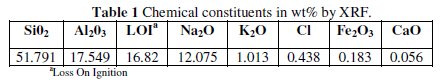
Zeolite used as substrate is of a A-type zeolite structure [41]; it has been synthesized in Islamic Azad University of Qaemshahr, Iran. Micro silica was first extracted from Equisetum arvense plant in North of Iran. It was calcined to 1300 °C for 4 h, which is beyond the dehydroxylation range. The requirement of silica was met from Equisetum arvense itself, and no other source was used for the same. Based on SEM image, the particle size of micro silica is about 1-4 μm. Sodium silicate was prepared by mixing 10 gr micro silica and 20 gr NaOH and charged into electrical furnace at 700 °C for 2 h. Zeolite A was prepared by adding sodium alumina to the reaction mixture and the reaction was maintained at 80 °C for 48 h. Finally the product was washed thoroughly with distilled water and dried at 150 °C (particle size of synthesized zeolite is about 300-500 nm). Also, the percentage elemental composition of zeolite has been presented by XRF technique in Table 1.
Preparation of MCPE
The Co-Z catalyst was prepared by mixing 0.5 g synthesized zeolite with 50 mL of 0.1 M cobalt nitrate solution and stirring at room temperature for 3 h. After cation exchange, Co-Z was filtered and washed with water until colorless water was obtained, and then dried in air.
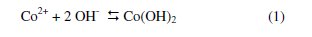
Carbon paste electrode containing Co-Z was obtained by homogeneously mixing of Co-Z and graphite particles and then paraffin oil was added drop-wise until a uniformly wetted paste was obtained. A portion of the prepared paste was packed into the end of a glass tube with a copper wire as electrical contact. The surface of paste was smoothed on a piece of paper. This electrode was named Co-ZMCPE. An electrode prepared with the same method but using zeolite was named ZMCPE. Finally, the Co-ZMCPE was immersed in 0.1 M NaOH solution and the potentials were cycled between -0.2 and 0.6 V vs. Ag/AgCl, KCl (3 M) at v = 50 mV s-1 until reproducible cyclic voltammograms were attained. In this solution, Co ions at the electrode surface will be converted into Co(OH)2 species according to the following reaction [42-45]:
Results and discussion
Electrochemical behavior of Co-ZMCPE
Fig. 1 shows the cyclic voltammograms of CPE, ZMCPE and Co-ZMCPE in 0.1 M NaOH solution at 20 mV s-1.
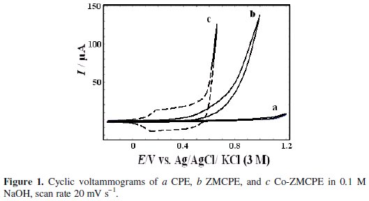
In Fig. 1, it can be seen that whereas neither oxidation nor reduction peaks are seen on CPE and ZMCPE, a well-developed redox wave was observed on the Co-ZMCPE. It can be attributed to the oxidation/reduction conversion between cobalt phases of Co(OH)2 and CoOOH, which are stable at alkaline pH [42-45], and in accordance with the following equation:

For ZMCPE, at positive potential of 0.5 V, there is a sharp rise of anodic current due to the evolution of oxygen. However, oxygen evolution reaction on ZMCPE appears at potentials less positive than CPE.
The effect of scan rate on electrochemistry of Co-ZMCPE is shown in Fig. 2a.
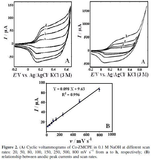
With an increasing scan rate, the peak current value of Co-ZMCPE increased linearly with the increasing scan rate in the range of 20-800 mV s-1 (Fig. 2b), indicating a surface-controlled process. From the slope of this line (Ip vs. v) , the electrode surface coverage (Γ*) can be calculated using the following equation, which is for the reversible process with the adsorbed species [46]:
where Ip, A, and Γ* stand for peak current, electrode surface area, and the surface coverage of the redox species, respectively. The total surface coverage of the immobilized active species was calculated as 1.2 × 10⁻⁹ mol cm-2.
Electrocatalytic oxidation of H2O2 at the surface of Co-ZMCPE
The electrooxidation of H2O2 was first studied at the surfaces of CPE and ZMCPE by cyclic voltammetric experiments in 0.1 M NaOH (Fig. 3a and Fig. 3b).
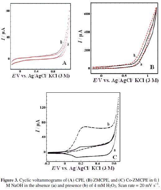
As it can be seen, the electrooxidation of H2O2 requires a large overpotential; no clear peak is observed in the range of -0.2 to 1.2 V on CPE or ZMCPE in 0.1 M NaOH solution containing H2O2.
However, by use of Co-ZMCPE, upon addition of H2O2 to the solution, the shape of the cyclic voltammogram of modified electrode changes dramatically with an increase of the oxidation current in potential of 0.25 V and a decrease of the cathodic peak current. This phenomenon is attributed to the production of Co(OH)2 and consumption of CoOOH, respectively. These results showed that the modified electrode has a high ability for H2O2 oxidation and the following mechanism can be proposed for the mediated electrooxidation of H2O2 at the surface of this modified electrode:


Optimization of the electrode variables for efficient performance of Co-ZMCPE
Effect of different percentages of Co-Z to graphite
Fig. 4 shows the effect of the paste composition on the resulting voltammetric response.
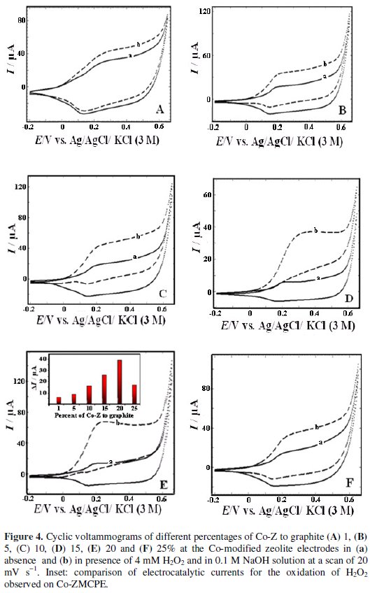
Co-ZMCPE with different percentages of Co-Z to graphite (1, 5, 10, 15, 20 and 25%) was studied in the presence and the absence of H2O2. There is an increase in the oxidation current peak density with increasing of percentages of Co-Z to graphite through a maximum at 20%. Accordingly, electrodes with this percentage were used in all the forgoing studies.
Effect of pH
The effect of pH on the electrochemical behavior of the modified electrode has been investigated in the presence and absence of hydrogen peroxide. The cyclic voltammetry responses of the modified electrode at different pH solutions are shown in Fig. 5.
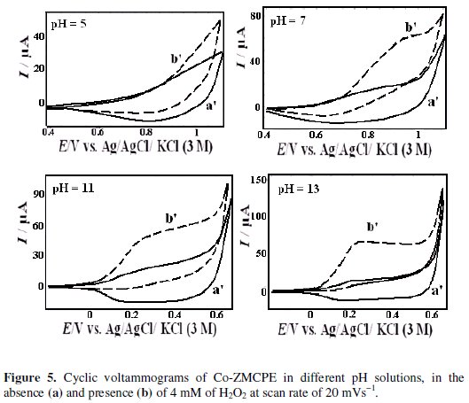
As can be seen, the peak potentials are shifted to less positive values with increasing the pH values. Also, the effect of pH on the catalytic oxidation behavior was investigated. No peak currents were observed at pH values below 5, probably due to the solution of cobalt oxide film (not shown) [45]. At pH values of 5-13, the modified electrode shows electrocatalytic activity. However, higher electrocatalysis peak currents are observed at pH 13.
Effect of H2O2 concentration
Fig. 6 shows the effect of H2O2 concentration on the cyclic voltammograms of the Co-ZMCPE.
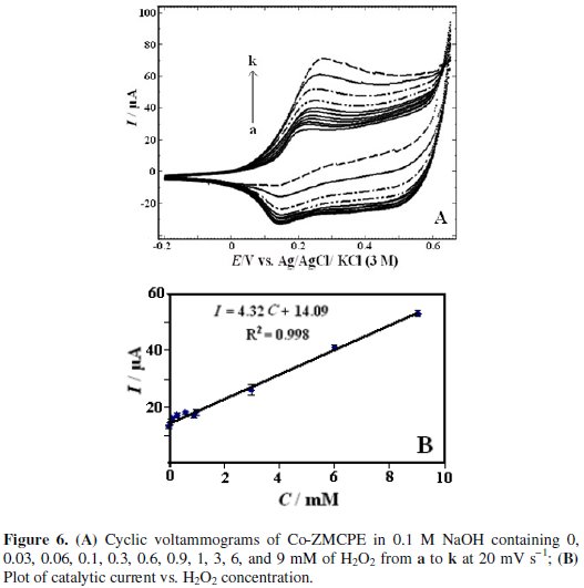
As can be seen from Fig. 6, the height of the anodic peak increases with increasing H2O2 concentration. The characteristic shape of CV in this potential region indicates that the signal is due to the oxidation of H2O2. The catalytic peak current is proportional to the concentration of H2O2 in the range of 0.03 to 9 mM. The linear regression equation is I (μA) = 4.32 (± 0.22) CH2O2 (mM) + 14.09 (± 0.71) (R2=0.998). The detection limit (LOD) with the signal-to-noise ratio of three calculated from the calibration graph was 0.017 mM H2O2.
Since amperometry under hydrodynamic condition is much more current sensitive than cyclic voltammetry, this method was employed in order to estimate the low detection limit. Fig. 7 displays the typical steady-state catalytic current time response of the rotated modified electrode (2000 rpm) with successive injection of H2O2 at an applied potential 0.42 V versus reference electrode.
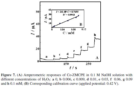
As shown in the figure a well-defined response was observed during the successive addition of H2O2. These results demonstrate a stable and efficient catalytic property of Co-ZMCPE. There is a linear relation between response current and peroxide concentration in the range 0.006 to 0.1 mM. The linear least squares calibration curve is I (μA) = 261.89 (± 1.4) CH2O2 (mM) + 0.7655 (± 0.02) with a correlation coefficient of 0.991. LOD (S/N=3), and sensitivity were 2.5 μM and 261.89 μA mM-1, respectively.
Chronoamperometric study
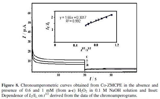
Chronoamperometry was used for the evaluation of the catalytic rate constant (k) for the chemical reaction between hydrogen peroxide and redox sites of surface Co-ZMCPE. Double step chronoamperograms of the redox process were recorded by setting the working electrode potential at 0.42 V (in first step) and 0.1 V (in second step) vs. Ag ∣ AgCl ∣ KCl (3 M) at different concentrations of hydrogen peroxide (Fig. 8a).
The rate constant for the chemical reaction between hydrogen peroxide and the redox sites of Co-ZMCPE was evaluated by the equation [47]:
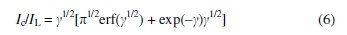
where IC is the catalytic current of hydrogen peroxide at Co-ZMCPE, IL is the limited current in the absence of hydrogen peroxide, and γ = k C0 t is the argument of the error function (C0 is the bulk concentration of hydrogen peroxide).
If γ exceeds 2, the error function is almost equal to 1 and the above equation can be simplified to
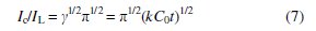
where k, C0, and t are the catalytic rate constant (cm3 mol-1 s-1), hydrogen peroxide bulk concentration (M), and time (s), respectively. The catalytic rate constant can be calculated from the slope of the IC/IL vs t1/2 plot. This plot was obtained from the chronoamperogram of Co-ZMCPE in the absence and presence of 1 mM hydrogen peroxide in 0.1 M NaOH (Fig. 8b). The mean value of k was found to be 8.67 × 105 cm3 mol-1 s-1. The results proved that Co- ZMCPE has good catalytic activity for hydrogen peroxide oxidation.
Interferences
Under optimal conditions, the interference of some compounds on the oxidation of 4 mM hydrogen peroxide in 0.1 M NaOH has been evaluated. The results show that 100-fold ascorbic acid and uric acid has almost no influences on voltammetric determination of hydrogen peroxide (signal change < 5%).
Stability of the modified electrode
After storing of the modified electrode for a week at room temperature, peak currents didn't change in the absence and presence of hydrogen peroxide. It confirms the stability of the modified electrode.
Conclusions
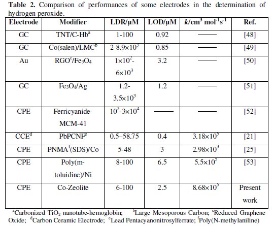
In this work, we have successfully constructed a novel composite with Co (II) impregnated zeolite. The Co impregnated zeolite was mixed with carbon paste to prepare a modified electrode (Co-ZMCPE). Hydrogen peroxide was employed as the probe to measure the electrochemical performance of Co-ZMCPE. It has been verified that Co-ZMCPE exhibits an excellent electrocatalytic activity. The results were investigated by cyclic voltammetry and chronoamperometry. The cyclic voltammograms showed that Co-ZMCPE increased the oxidation current of hydrogen peroxide as compared to CPE and ZMCPE and anodic peak currents increased with adding of hydrogen peroxide. Also, the catalytic rate constant was obtained from the chronoamperograms. The values of LOD, LDR (linear dynamic range) and k for hydrogen peroxide determination at this modified electrode are comparable with those obtained by using other modified electrodes (Table 2).
References
1. Mravec D, Hudec J, Janotka I. Chem Pap. 2005;59:62. [ Links ]
2. Yanshuo L, Weishen Y. J Mem Sci. 2008;316:3. [ Links ]
3. Jacobs P A, Martens J A. Synthesis of high silica aluminosilicate zeolites; studies in surface science and catalysis. Amsterdam: Elsevier; 1987. Vol.33. [ Links ]
4. Occelli M L, Rosson H E. Zeolite synthesis. in Proceedings of the ACS. Symposium Series. Washington, DC: American Chemical Society; 1989. Vol 398. [ Links ]
5. Mosqueda-Jimenez B I, Jentys A, Seshan K, et al. J Catal. 2003;218:348. [ Links ]
6. Manea F, Pop A, Radovan C, et al. Sensors. 2008;8:5806. [ Links ]
7. El-Shafei A A, Abd Elhafeez A M, Mostafa H A. J Solid State Electrochem. 2010;14:185. [ Links ]
8. Zimmer A, Monter D, Reschetilovski W. J Appl Electrochem. 2003;33:933. [ Links ]
9. Samant P V, Fernandes J B. J Power Sources. 2004;125:172. [ Links ]
10. Schuvailo O M, Soldatkin O O, Lefebvre A, et al. Anal Chim Acta. 2006;110:573. [ Links ]
11. Lobnik A, Cajlakovic M. Sensors Actuators B. 2001;74:194. [ Links ]
12. Westbroek P, Van Haute B, Temmerman E. Fresen J Chem. 1996;354:405. [ Links ]
13. Liu X, Xu Y, Ma X, et al. Sensors Actuators B. 2005;106:284. [ Links ]
14. Li J, Dasgupta PK, Tarver GA. Anal Chem. 2003;75:1203. [ Links ]
15. Rapoport R, Hanukoglu I, Sklan D. Anal Biochem. 1994;218:309. [ Links ]
16. Pappas A C, Stalikas C D, Fiamegos Y C, et al. Anal Chim Acta. 2002;455:305. [ Links ]
17. Fernandez-Romero J M, Lugue De Castro M D. Anal Chem. 1993;65:3048. [ Links ]
18. Marquette C A, Blum L J. Anal Chim Acta. 1999;381:1. [ Links ]
19. Nozaki O, Kawamoto H. Luminescence. 2000;15:137. [ Links ]
20. Lu J, Lau C, Morizono M, et al. Anal. Chem. 2001;73:5979. [ Links ]
21. Razmi H, Heidari H. J Electroanal Chem. 2009;625:101. [ Links ]
22. Lin Y, Cui X, Li L. Electrochem Commun. 2005;7:166. [ Links ]
23. Guascitoa MR, Filippo E, Malitesta C, et al. Biosens Bioelectron. 2008;24:1057. [ Links ]
24. Yang Y, Mu S. Biosens Bioelectron. 2005;21:74. [ Links ]
25. Ojani R, Raoof JB, Norouzi B. J Solid State Electrochem. 2010;14:621. [ Links ]
26. Ojani R, Raoof JB, Norouzi B. Int J Electrochem Sci. 2012;7:1852. [ Links ]
27. Lvovich V, Scheeline A., Anal Chem. 1997;69:454. [ Links ]
28. Wang GH, Zhang LM. J Phys Chem B. 2006;110:24864. [ Links ]
29. Lin XQ, Chen J, Chen ZH. Electroanalysis. 2000;12:306. [ Links ]
30. Kafi AK, WuG, Chen A. Biosens Bioelectron. 2008;24:566. [ Links ]
31. Gavalas VG, Chaniotakis NA. Anal Chim Acta. 2001;427:271. [ Links ]
32. Gavalas VG, Chaniotakis NA. Anal Chim Acta. 2000;404:67. [ Links ]
33. Giahi M, Aghaie H, Arvand M, et al. Russian J Electrochem. 2005;41:1290. [ Links ]
34. Arvand M, Ansari R, Heydari L. Mater Sci Eng C. 2011;31:1398. [ Links ]
35. Enea O. Electrochim Acta. 1989;34:1647. [ Links ]
36. Arvand M, Zanjanchi MA, Islamnezhad A. Anal Lett. 2009;42:727. [ Links ]
37. Mazloum-Ardakani M, Akrami Z, Kazemian H, et al. Int J Electrochem Sci. 2009;4:308. [ Links ]
38. Onyestyak G, Valyon J, Papp K. Mater Sci Eng A. 2005;412:48. [ Links ]
39. Murray CG, Nowak RJ, Rolison DR. J Electroanal Chem Interfacial Electrochem. 1984;164:205. [ Links ]
40. Shaw BR, Creasy KE, Lanczycki CJ, et al. Electrochem Soc. 1988;135:869. [ Links ]
41. Meier WM. Pure Appl Chem. 1986;58:1323. [ Links ]
42. Vittal R, Gomathi H, Rao GP. J Electroanal Chem. 2001;497:47. [ Links ]
43. Sun CY, Zhu YG, Zhu TJ, et al. J Solid State Electrochem. 2013;17:1159. [ Links ]
44. Liang Y, Bao S, Li H. J. Solid State Electrochem. 2007;11:571. [ Links ]
45. Salimi A, Hallaj R, Soltanian S, et al. Anal Chim Acta. 2007;594:24. [ Links ]
46. Bard AJ, Faulkner LR. Electrochemical methods, fundamentals and applications. New York: Wiley;2001. [ Links ]
47. Lavirone E. J Electroanal Chem. 1979;101:19. [ Links ]
48. Guo C, Hu F, Li CM, et al. Biosens Bioelectron. 2008;24:819. [ Links ]
49. Lu J, Ju J, Bo X, et al. Electroanalysis. 2013;25:2531. [ Links ]
50. Ye Y, Kong T, Yu X, et al. Talanta. 2012;89:417. [ Links ]
51. Liu Z, Zhao B, Shi Y, et al. Talanta. 2010;81:1650. [ Links ]
52. Ojani R, Raoof J B, Fathi S. J Solid State Electrochem. 2009;13:837. [ Links ]
53. Ojani R, Raoof J B, Babazadeh R. Electroanalysis. 2010;22:1607. [ Links ]
*Corresponding author. E-mail address: norouz2020@yahoo.com
Received 25 March 2015; accepted 18 April 2015

