


Services on Demand
Journal
Article
 English (pdf)
 Article in xml format
 Article references
 Send this article by e-mail
Indicators
-
 Cited by SciELO
 -
 Access statistics
Related links
-
 Similars in
SciELO
Similars in
SciELO
Share

 Permalink
Portugaliae Electrochimica Acta
Print version ISSN 0872-1904
Port. Electrochim. Acta vol.35 no.1 Coimbra Jan. 2017
https://doi.org/10.4152/pea.201701053
Influence of Organic Additives and of Stabilized Polymeric Micelles on the Metalographic Structure of Nanocomposite Zn and Zn-Co Coatings
N. Boshkov*
Institute of Physical Chemistry, ''Academik G. Bonchev'', bl. No. 11, Bulgarian Academy of Sciences, Sofia 1113, Bulgaria
Abstract
The peculiarities of the metallographic structure of electrodeposited nanocomposite polymeric modified Zn and Zn-Co (1 wt.%) alloy coatings are described and discussed. These coatings are obtained from usual electrochemical baths for Zn and Zn-Co alloys, but with the addition of stabilized polymeric micelles (SPM). The latter are of core-shell type, and are based on polypropylene oxide (hydrophobic core) and polyethylene oxide (hydrophilic shell). These coatings and their polymeric modified nano-composites are investigated with X-ray (XRD) method, which reveals changes in the metallographic structure as a result of the presence or absence of organic additives (wetting agent and brightener) and SPMs. The possible reasons for the changes observed are commented. In addition, cyclic voltammetry method (CVA) is applied in order to clarify the influence of the applied additives and of SPM on the cathodic (deposition) and anodic (dissolution) processes.
Keywords: zinc; Zn-Co alloy; metallographic structure; polymeric modified coatings.
Introduction
Zinc coatings are widespread in the industry as they are used as sacrificial layers for protection of steel against corrosion. Generally, zinc content in the earth crust is below 0.01 wt%, and this metal is the 24th most abundant element in the world. Zinc coatings are corrosion resistant in the pH range 7 - 12, and they are hopefully able to protect the steel substrate, for example, at atmospheric conditions.
According to the significant application of Zn on industrial scale for corrosion protection of different steel parts (nuts, bolts, metal brackets, etc.) and components, this metal is the forth-most commonly used one, only surpassed by iron, copper and aluminum [1-5]. Zinc coatings find application in the automotive industry, but also in civil engineering, household, etc. The global prospects for the automotive industry are for the production of approximately hundred million cars in 2018, and the main construction material used for this purpose is galvanized low carbon steel. Another aspect of the zinc application is its lower cost compared to other industrial materials. The safe exploitation of the zinc is, to a certain degree, limited, due to the aggressive nature of an environment that contains industrial pollutants, which requires additional efforts to increase corrosion resistance [6-9]. For example, the alloying of Zn with some metals, such as Mn, Co, Ni, etc., can be applied for this purpose. However, the protective characteristics of the galvanic alloys often need additional improvement, especially in more aggressive media.
A possible way to extend the service life of the zinc is obtaining composite coatings by using different inorganic (oxides, ceramics, carbides, such as ZrO2, TiO2, SiO2, Fe2O3, SiC etc) [10-14] or polymeric micro-(nano)particles, which generally also exhibit high corrosion resistance [15-19]. One serious problem could be the possible agglomeration of the particles in the electrolyte, and their sedimentation on the bottom. The amounts of the incorporated particles in the metal matrix depend in general on their concentration in the electrolytic bath, on the additives used, and on the electrodeposition conditions. In addition, Zn and its alloy coatings have various morphologies and textures [2-5], which can seriously affect their protective and physical-mechanical properties.
The main aim of the present work is to characterize and discuss the influence of the stabilized polymeric micelles (SPM) on the metallographic structure, and on the deposition process of nanocomposite Zn and Zn-Co (1 wt.%) coatings.
Experimental
Sample and electrolyte preparation
The composite and non-composite zinc and Zn-Co (1 wt.%) coatings are electrodeposited on low carbon steel sheets (sizes 2 × 1 × 0.1 cm; surface area of 4 cm2) with a coating thickness of about 12 μm. The electrodeposition process is carried out at ambient room temperature of 25 °C and current density of 2 A.dm-2. Metallurgical zinc plates are used as anodes; no stirring or circulation is applied.
The electrolytes for obtaining the nanocomposite coatings are ultrasonically treated before the electrodeposition during 10 minutes, aiming a better distribution of the SPM in the entire volume.
Non-composite coatings
Electrodeposited zinc coatings are obtained at pH value 4.5-5.0 from starting electrolyte (SE) with a composition 150 g/L ZnSO4.7H2O, 30 g/L NH4Cl, 30 g/L H3BO3 and additives AZ-1 (wetting agent -50 mL.L) and AZ-2 (brightener -10 mL/L).
Electrodeposited Zn-Co (1 wt.%) alloy coatings are obtained from starting electrolyte (SE1) containing 100 g/L ZnSO4.7H2O; 120 g/L CoSO4.7H2O; 30 g/L NH4Cl; 25 g/L H3BO3 at pH 3.0-4.0 and additives ZC-1 (wetting agent 20 mL/L) and ZC-2 (brightener -2 mL/L).
Composite coatingss
The composite Zn and Zn-Co (1 wt.%) coatings are electrodeposited from SE and SE1 at the same electrodeposition conditions described above, but with an addition of nano-sized SPM. The latter are based on PEO75PPO30PEO75 (polyethylene oxide - poly-propylene oxide - poly-ethylene oxide) tri-block copolymer, where PPO forms the hydrophobic core, and PEO the hydrophilic shell of the micelle.
Stabilized polymeric micelles (SPM)
The main procedure for SPM preparation is described elsewhere [20]. It is based on the formation of core-shell type micelles in aqueous media at 60 oC, and immobilization of tetra-functional hydrophobic monomer - pentaerythritol tetraacrylate (PETA) -, followed by UV-induced polymerization and formation of a semi-interpenetrating polymer network. The stabilized polymeric micelles are dialyzed against distilled water, and then added to SE or SE1 in concentration of 0.1 wt.% [15, 16].
Sample characterization and reproducibility
The metallographic structure and the changes appeared in the metal matrix as a result of the incorporated SPM are determined with X-ray diffraction analysis using of DRON-3 unit (Bragg-Brentano arrangement, CuKα -radiation and scintillation counter).
The influence of the SPM added to the electrolytic baths on the cathodic and anodic processes is investigated with the cyclic voltammetry method. The measurements are performed with an electrochemical workstation PAR ââVersaStat 4'' at scan rate of 10 mV.s-1 in a common three-electrode experimental cell (250 mL). Platinum plate is taken as a counter electrode, and the potentials are measured with respect to saturated calomel electrode (SCE). The results from the investigations are, in average, of 5 samples per type and per stage, i.e., for each measurement 5 replicates of a Zn and Zn-Co alloy, as well as of their composites, are conditioned for initial and follow-up measurements.
Results and discussion
XRD investigations
The results obtained by XRD method for electrodeposited Zn and polymeric modified Zn coatings are demonstrated in Fig. 1 (A - D).
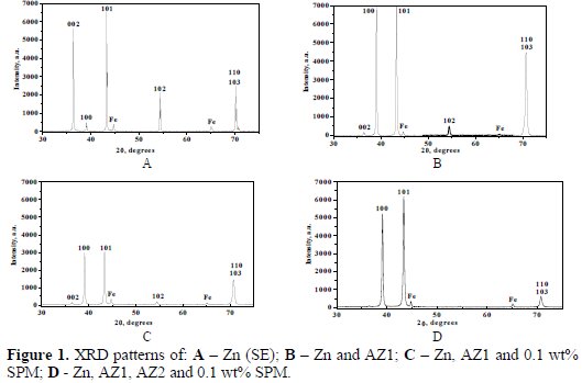
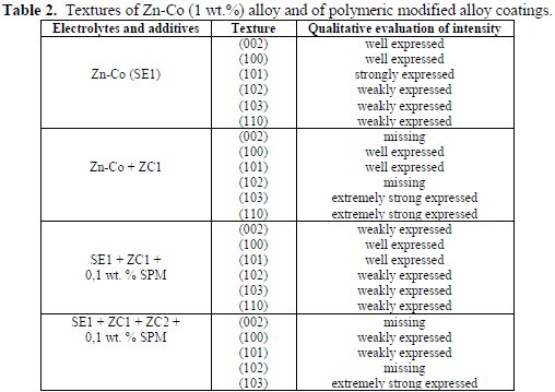
X-ray diffraction method allows qualitatively characterizing the type of the texture, as well as the evaluation of its intensity. If several orientations appear, it can be assessed whether one is stronger than another. The textures registered for the electrodeposited Zn and for the composite (polymeric modified) zinc coatings, as well as the qualitative evaluation of their intensity, are presented in Table 1.
It is well known that the electrodeposition process of the metal cations from the electrolytic bath significantly depends on their discharge and on the applied additives (mainly organic) which can affect the cathode polarization, either by control of the electron transfer or by preferential adsorption on the surface.
According to Fig. 1 and Table 1, it is obvious that the zinc coating obtained from a bath without additives (SE) has a strongly expressed diffraction intensity of (002) and (101) peaks. The diffraction lines corresponding to (102), (103) and (110) planes - which practically overlap - are well expressed, but with lower intensity compared to both (002) and (101), respectively. Finally, the diffraction peak corresponding to (100) plane has the lowest intensity and is weakly expressed (Fig. 1A).
When the wetting agent is added to SE the crystallographic orientation of the electrodeposit changes - the peaks corresponding to textures (002) and (102) are strongly reduced. Simultaneously, the peaks characterizing (100) and (101) planes strongly increase. The same, although to a lesser extent, is true for (103) and (110) preferred orientations. The obtained results are a sign of the strong influence of the additive AZ1 on the texture of the zinc coating (Fig. 1B). According to the presented results, in Fig. 1C it can be summarized that, in the presence of AZ1, the SPM qualitatively changes the texture of the coating. In that case the intensity of the peaks corresponding to (100), (101), (102), (103) and (110) planes decreases to a different extent, while the intensity of (002) remains almost the same.
In the presence of both additives AZ1 and AZ2, as well as of SPM (Fig. 1D), the intensity of the peaks corresponding to (100) and (101) planes increases about 1.5 and 2 times, respectively, compared to Fig. 1C. In that case, the intensity of the preferred orientations (103) and (110) decreases, while the peaks corresponding to orientations (002) and (102) practically disappear. Most probably, the reason for this observation seems to be the more pronounced impact of AZ2 (brightener) leading to the appearing of more grains with smaller sizes, which grow evenly in preferred directions.
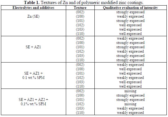
The textures of electrodeposited Zn-Co (1 wt.%) and of polymeric modified alloy coatings are demonstrated in Table 2, and the XRD patterns of the samples in Fig. 2.
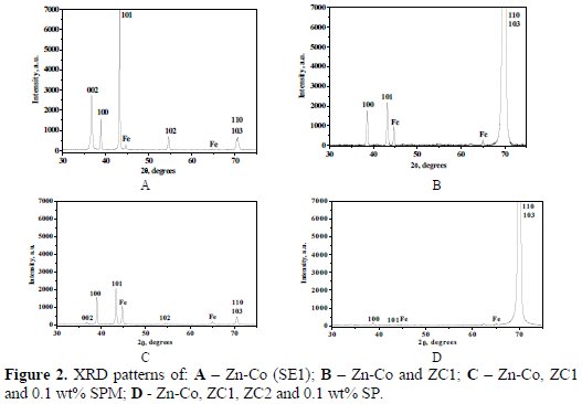
The results for the alloy coatings obtained from SE1 (Fig. 2A) clearly demonstrate the quality match with Zn obtained from SE, although with different intensity. The intensity of (002) peak is about two times lower, and that of (100) - about 1.5 times stronger expressed. The diffraction lines corresponding to (102), (103) and (110) planes are about two times weakly expressed, while the intensity of (101) peak is almost the same (Fig. 1A and 2A). When the wetting agent is added to SE1 (Fig. 2B), the crystallographic orientations change - the peaks corresponding to (110) and (103) planes increase extremely strongly, while the texture (101) decreases about 3 times. The peak corresponding to (100) plane slightly increases, and the peak for (002) plane disappears.
In the presence of the wetting agent ZC1, the SPM strongly affects the texture of the alloy (Fig. 2C and 2B). The intensity of the peaks corresponding to (110) and (103) sharply decreases, while these reappear for (002) and (102) (compared with Fig. 2A). The intensity of the preferred orientations (100) and (101) remains almost unchanged.
In the presence of both additives (wetting agent and brightener), the adding of SPM to the electrolytic bath drastically changes again the alloy texture, and the result is an extremely strong intensity of the peaks for (110) and (103) planes, and a sharp decrease of (100) and (101) orientations (Fig. 2D). The peaks for (002) and (102) planes are missing. It can be concluded that, in the case of Zn- Co alloy, the influence of SPM is much more pronounced compared to the Zn, since its presence strongly affects the intensity of (110) and (103) orientations.
Cyclic voltammetry
Fig. 3 demonstrates the influence of SPM on the cathodic and anodic processes in SE and SE1, in the presence of a wetting agent.
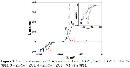
The cathodic process of zinc deposition begins at about -1210 mV, and proceeds with a relative high speed (steeper slope) up to 1320 mV (curve 1); see the inset. Thereafter, the deposition rate slightly slows down until -1450 mV, and the direction of the change of the polarization shifted from cathodic-going to anodic-going. This behavior is probably related to the influence of the wetting agent, which leads to the appearance of a definite number of grains on the cathode, followed by their increase in size.
In the presence of SPM (curve 2), a slightly expressed over-polarization effect can be observed - the deposition process begins at about -1255 mV, most probably due to the partial blocking effect of SPM on some parts of the cathode surface. The process proceeds with a higher speed up to -1380 mV, and thereafter slows down (changes the slope) until -1400 mV. During the return move in the direction of the anodic zone, curves 1 and 2 practically overlap at about -1100 mV.
In the presence of AZ1, the SPM leads to a shift of the anodic maximum to a more negative potential value -curve 2 (-780 mV) and curve 1 (-685 mV), respectively. The current density is also affected: 192 mA.cm-2 for Zn, and 349 mA.cm-2 for the composite one. This means that the anodic dissolution rate of the composite coating is higher. A probable explanation for this result could be the absence of the brightener in both electrolytes, which leads to a greater surface inhomogeneity of the composite coating.
It must be noted that the SPM added to the electrolytic bath is not made of hermetic closed capsules. They have been received from amphiphilic tri-block copolymer type PEO-PPO-PEO -poly (ethylene oxide) - block -poly ( propylene oxide) - block -poly (ethylene oxide) [20]. The hydrophobic core consists of closely interwoven PPO-segments, while the hydrophilic shell is dominated by hydrated PEO-chains, which allow the penetration of the solution into the bulk of the shell, i.e., permeation of zinc and other ions.
On the other hand, there are some literature data [21] on the affinity of the polyethylene oxide for positively charged metal ions (such as zinc). The result will be a coordination bond between these ions and the oxygen from the PEO- chains.
Having this point in mind, it can be suggested the appearance of some positively charged polymeric/zinc aggregates, which will be deposited on the cathode during the electrodeposition. Their size will be much greater compared to the individual zinc ions, and these aggregates will cover a bigger place on the cathode during the electrodeposition of the composite coatings.
In addition, due to their small sizes, part of the zinc ions could locate in the PEO shell without interacting with it (the ions will practically be spatially positioned between the separate hydrophilic segments/chains). When the current flows these ions will be simultaneously directed to the cathode, setting off (bringing with) the already formed aggregates. Finally, both individual zinc ions and polymeric/zinc aggregates will simultaneously deposit on the cathode, leading to the appearance of a composite coating.
In SE1 with the wetting agent, whether in the presence (curve 4) or absence (curve 3) of SPM, the electrodeposition of Zn-Co alloy begins at about -1120 mV, i.e., at more positive potentials, compared to Zn and its composite. The curves of both coating types have a steeper slope, i.e., the process is accelerated, compared to curves 1 and 2, respectively. In the anodic part, several peaks appear corresponding to the dissolution of some intermediate products/phases of both metals (Zn and Co) present on the cathode. The occurrence of positively charged polymeric/metal (Zn or Co) aggregates in the electrolytic bath, due to the reasons mentioned above during the electrodeposition process, also takes place here.
Fig. 4 shows the influence of SPM on the cathodic and anodic processes for Zn and Zn-Co, in the presence of wetting agent and brightener.
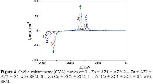
The addition of the brightener changes the course of the cathodic curves of the zinc - 1 and 2. The deposition process for both zinc and composite zinc coatings is characterized by a strong over-polarization, compared to Fig. 3, and begins at potential value of 1350 mV. In that case, the aesthetics of the coatings is better -they are finely crystalline, since the rate of nucleation is greater, compared to the rate of growth. The current density value registered at the vertex potential is greater for the composite zinc (-29 mA.cm2), compared to the non-composite one (-17 mA.cm 2), but much lower, compared to the same parameter from Fig. 3 (-85 mA.cm-2). The presence of SPM does not affect the polarization of the process at the initial stages, i.e., no effect of over-polarization or depolarization can be observed, and both cathodic curves practically overlap at this stage. The reverse stroke of the curves takes place on its own substrate (already deposited coating), and the process, in that case, is depolarized -curves 1 and 2. Simultaneously, the anodic dissolution rate drastically decreases, compared to Fig. 3, i.e., 41 mA.cm-2 for Zn and 76 mA.cm-2 for the composite one can be registered. The anodic peak of the zinc is placed at 695 mV, while that of the composite one is at 720 mV.
In the case of Zn-Co, the deposition process begins at about -1275 mA.cm-2 for Zn-Co, and at -1200 mA.cm-2 for the composite alloy, i.e., a depolarization effect appears in the presence of SPM. The cathodic processes are accelerated compared to the Zn and its composite, having in mind the curve slopes.
The cathodic current density of the composite Zn-Co is greater - about -65 mA.cm, compared to the non-composite one, which is -45 mA.cm. These values are close of the anodic peaks: 45 mA.cmfor Zn-Co, and 75 mA.cmfor the composite one. The potentials are close: about 835 mV for Zn-Co, and 820 mV for the composite. The additional slightly expressed anodic peak appears for both coatings at -375 mV.
Conclusions
According to the presented results the following can be summarized:
- The addition of the wetting agent to SE leads to an increase of the peaks corresponding to (100), (110) and (103) planes. In the presence of AZ1, the SPM quantitatively changes the metallographic structure of the Zn coating, decreasing the diffraction intensity of the peaks, corresponding to (100) and (101) planes. With the simultaneous presence of both wetting agent and brightener, SPM leads to an increase in the intensity of the preferred orientations (100) and (101), and to a slight decrease of (103) and (110). The (002) texture practically disappears
- In the case of Zn-Co, the addition of wetting agent to SE1 leads to a strong increase in the intensity of the peaks representing (110) and (103) orientations, to a decrease of (101), and to the disappearance of (002) texture. In the presence of ZC1, the SPM leads to an extremely strong decrease in the intensity of the preferred orientations (110) and (103), compared to the non-composite Zn-Co. The intensity of the texture (101) and (100) remains almost unchanged. In the presence of both additives the SPM leads to an extremely strong increase in the intensity of the peaks corresponding to (110) and (103) planes.
- In the presence of the wetting agent, SPM slightly affects the course of the cathodic processes for Zn and Zn-Co alloy. Their influence is strongly demonstrated in the anodic region for the zinc. SPM practically does not affect the anodic curve of the Zn-Co alloy.
- In the presence of both additives, SPM leads to an over-polarization effect in the cathodic region for Zn, compared to the case when only the wetting agent is present in the bath.
- In the presence of both additives, SPM leads to a depolarization effect of the cathodic curve of the composite Zn-Co alloy, compared to the galvanic one. The anodic current densities of the composite coatings are greater compared to the non-composite ones.
References
1. Gomes A, Pereira MIS. Electrochim Acta. 2006;51:1342. [ Links ]
2. Vasilakopoulos D, Bouroushian M, Spyrellis N. J Mater Sci. 2006;41:2869. [ Links ]
3. Raeissi K, Saatchi A, Golozar MA. J Appl Electrochem. 2003;33:635. [ Links ]
4. Raeissi K, Saatchi A, Golozar MA, et al. J Appl Electrochem. 2004;34:1249. [ Links ]
5. Vasilakopoulos D, Bouroushian M, Spyrellis N. Electrochim Acta. 2009;54:2509. [ Links ]
6. Tuaweri TJ, Wilcox GD. Surf Coat Technol. 2006;200:5921. [ Links ]
7. Muller C, Sarret M, Benballa M. Surf Coat Technol. 2003;162:49. [ Links ]
8. Praveen BM, Venkatesha TV, Naik YA, et al. Surf Coat Technol. 2007;201:5836. [ Links ]
9. Vathsala K, Venkatesha TV. Appl Surf Sci. 2011;257:8929. [ Links ]
10. Tulio PC, Rodrigues SEB, Carlos IA. Surf Coat Technol. 2007;202:91. [ Links ]
11. Nemes PI, Lekka M, Fedrizzi L, et al. Surf Coat Technol. 2014;252:102. [ Links ]
12. Praveen BM, Venkatesha TV. Appl Surf Sci. 2008;254:2418. [ Links ]
13. Praveen CM, Venkatesha TV, Chandrappa KG. Surf Coat Technol. 2012;206:2249. [ Links ]
14. Tseluikin VN, Koreshkova AA. Russ J Appl Chem. 2014;87:1251. [ Links ]
15. Boshkov N, Tsvetkova N, Petrov P, et al. Appl Surf Sci. 2008;254:5618. [ Links ]
16. Boshkov N, Koleva DA, Petrov P, et al. Corrosion resistant nano-composite metallic coatings with embedded polymeric aggregates. In: Magagnin L, editor. Engineered Metal Matrix Composites: Forming Methods, Material Properties and Industrial Applications. Chapyer 10. NOVA Publishing House; 2013. p. 261.
17. Koleva D, Boshkov N, Bachvarov V, et al. Surf Coat Technol. 2010;204:3760. [ Links ]
18. Koleva DA, Taheri P, Tsvetkova N, et al. ECS Transactions. 2011;33:8592. [ Links ]
19. Pazderova M, Bradac M, Vales M. MM Science J. 2010;208. [ Links ]
20. Petrov P, Bozukov M, Tsvetanov Ch. J Mater Chem. 2005;15:1481. [ Links ]
21. Yang H, Farrington GC. Technical Report No.: 1992-24. J Electrochem Soc. 1991.63
*Corresponding author. E-mail address: NBoshkov@ipc.bas.bg
Received October 12, 2016; accepted November 8, 2016

