


 Inglês (pdf)
 Artigo em XML
 Referências do artigo
 Enviar este artigo por email
 Citado por SciELO
  Similares em
SciELO
Similares em
SciELO 
 Permalink
Introduction
W and Co are strategic metals, due to their inherent properties and critical applications. W carburization by C generates WC, which, when mixed with Co by powder metallurgical route, via a liquid phase sintering process, produces cemented WC-Co. This alloy possesses exotic properties, such as very high hardness, excellent wear resistance, superior toughness and outstanding corrosion resistance 1. Due to these properties, WC-Co finds applications in cutting tools, seal rings, drill bits, and various mining equipment. Table 1 shows general characteristics of W, C and WC-Co.
Table 1 Some characteristics of WC-Co and its constituent metals.
| Symbol | W (atomic) | Co (atomic) | WC-Co |
|---|---|---|---|
| Mass (g/Mol.) | 183.86 | 58.93 | 195.86 |
| Bulk density (g/cm3) | 19.3 | 8.90 g/cm3 | 15.63 |
| Melting point (ºC) | 3410 | 1495 | 2870 |
| Boiling point (ºC) | 5530 | 2927 | 6000 |
| Solubility in water | - | - | Insoluble |
| Nominal specific gravity (g/cc) | 19.25 | 8.92 | 14.29 |
| Particle shape | - | - | Irregular |
| Appearance | - | - | Grey-black lustrous solid |
| Crystallography | BCC | HCP | Hexagonal |
However, WC-Co materials have often worn out and failed, due to extreme environmental conditions 2 during drilling or tunnel construction, for various industries, such as oil, gas, petroleum and mining exploration 1. As the global consumption of these materials grows due to an increasing population, the requirement for manufactured goods will also rise. Since W and Co are rare and valuable materials, and their extraction is also energy extensive and costly, many potential sources of WC-Co based scraps could be turned out into valuable secondary resources 3. These sources include worn-out discarded or failed WC-Co tool bits (from cutting, drilling and mining) and machining scraps. WC scraps also come from wear-resistant parts and high-temperature applications, such as turbine blades, jet nozzles, or other parts removed from jet engines, hard metal residues, tailings, machined chips, grindings and armament industry (various anti-aircraft and anti-missile warheads/ammunition). Hence, various types of W scraps are generated, either during the manufacturing of W alloys materials, or at the end of their service life 1,4. The recycling of scrapped WC, W and Co alloys has numerous benefits, due to the following reasons: (i) W and Co concentration in ores is considerably lower (30-99%) than that of their various types of scraps, which results in their high-cost extraction, and in the emission of toxic gases; associated elements in scraps do not cause severe problems during chemical processing; and contaminated metal contents are lower and better known in scraps than in ores. So, WC-Co scrapped materials recycling would be eco-friendly and more economical than extracting these metals from the ore. Hence, scrapped WC-Co materials can be embodied as an excellent secondary resource, with a view of recovering these metals, which can be considered strategically very important, in order to cut the emission of toxic gases and save time (5). Besides, statistics reveal that approxim. 20 to 30% of the total supply of recovered W and Co may drop the raw material cost by about 15 to 50% 6.
Although several recycling processes have been globally developed and used, their success would depend on their eco-friendliness and economic feasibility 5. These processes include pyrometallurgy-based oxidation, carbothermal reduction 7,8 hydrometallurgy 9,10 and electrometallurgy 11-18 routes, or their combination 19-21, in order to recover the valuables W and Co materials. Researchers 4 have also studied pyrometallurgy 8, hydrometallurgy 10,22 or pyro/hydrometallurgy 19) methods, and compared them based on energy consumption, eco-friendliness, equipment cost, emission of toxic gases and recovery of different products (e.g., W and Co) 23.
The major pyrometallurgical-based recycling processes are Zn melting 24,25, cold streaming, chemical modification, alkali leaching 26, oxidation roasting followed by leaching 19, chlorination, high-temperature smelting, molten salts electrolysis 27, etc., of which majority involves the use of expensive chemicals (acids, bases, and inorganic salts). A mechano-chemical reaction-based recycling process, in which the scrapes were thermally oxidized at 600 ºC, followed by grinding in NaOH, and water leaching, has also been developed 29.
Zn melting allows a direct conversion of the waste containing WC into a usable powder, by Co selective dissolution in a molten Zn bath. Although it (and also cold streaming) does not involve the numerous steps of conversion, extraction, precipitation, etc., from other methods, which increase the recycling time and costs, Zn melting is not economical, since it involves crushing (grinding, milling) scraps, also demanding much energy. Further refining by chemical modification is essential to attain more pure W, but it requires large-scale equipment, more expensive than the direct recycling practice, and it yields a relatively slow reaction rate 28.
Therefore, the pyrometallurgical-based processes suffer from disadvantages, such as high energy consumption, emission of toxic gases that cause pollution, and stringent air filtration.
On the other hand, hydrometallurgical methods involve the use of corrosive and concentrated acids for dissolving WC-Co material of the refractory type. Besides, they usually require subsequent separation and purification processes, which are also relatively time-consuming.
Electrochemical-based recycling methods have advantages over hydrometallurgical and pyrometallurgical processes, such as lower energy consumption, higher efficiency, lower costs, and less industrial requirements 4. So, since suitable electrochemical recycling processes, in order to recover pure W and Co from WC-Co scrap materials, are fundamental 30, the interested research community has started their development, by collecting and sorting WC scraps.
In an electrochemical process, the WC-Co scraps act as the anode, and graphite or SS are used as the cathode. During electrolysis, the anode and cathode are dipped into the selective electrolyte. A DC power source provides the power supply to the electrochemical cell, in which the positive and negative terminals are connected to the anode (scrap materials) and the cathode, respectively. During electrolysis, the anodic material dissolution starts, and both Co and W dissolve in a solution containing their ions. Two different types of electrochemical recycling techniques based on HCl, HNO3, H2SO4, H3PO4 and alkali electrolytes (NaOH and NH3) have been adopted in the WC-Co scrap electrodissolution. It has been found that W and Co effective recovery depend on the selective phase dissolution and deposition mechanisms 6,15,16,19,28,31-37. However, in an acidic medium, Co is dissolved and goes into the electrolyte, and a significant fraction of it is deposited on the cathode, leaving behind the WC skeleton as an anode residue, which is further processed. After dissolution, the undissolved WC anode residue materials are obtained from the bottom of the cell and, then, subjected to crushing and drying, in order to obtain, by electroextraction, the W powder. However, the remaining Co is simultaneously deposited on the cathode or removed from the electrolyte, by using the electrowinning process.
The foremost constraints of this technique are that it is time consuming, still suffers from anodic passivation, and its use of aggressive chemicals causes the corrosion of costly equipment. This makes the procedure relatively inefficient and more expensive than the pyrometallurgical-based process. However, the main benefit of this technique is to obtain very pure W and Co, in a single-step direct recycling process 6,37. On the other hand, WC scrap electrodissolution in a NaOH electrolyte has constraints, since this electrolyte recycling is impossible, and further conversion of Na2WO4 into H8N2O4W is very time-consuming. Alternatively, the WC-Co scraps have also been treated in an alkali medium of NH4OH (high pH), because W and Co are highly soluble in it, forming H8N2O4W or APT and Co amine complexes 12,16,19,34. Further processing of the obtained APT, at high temperatures, under H2 gas, leads to the formation of W powder 38. However, it has also been reported that the anodic passivation retards the scrap dissolution and adversely affects metals recovery 28.
Considering these facts, a systematic study on cemented WC scrap electrodissolution in NH3 electrolytes has been carried out, in order to develop an improved process for the recovery of valuable refractory and strategic metals, such as W and Co. PDP tests were conducted for understanding the WC-Co scrap electrochemical anodic dissolution mechanisms and passivation behavior. PDP also indicated the suitable electrolyte composition and the best additives, so as to ensure the WC-Co samples uninterrupted dissolution. AFM micrographs have confirmed the dissolution mechanisms, and their extent, based on the Ra value. The YTO and Co metals were obtained by the subsequent electrolyte processing.
Experimental procedures
Testing material and chemicals
Cemented WC-Co tool bits scraps
Cemented WC-Co tool bits were supplied by M/s Bharat Futuristic Pvt. Ltd, Bangalore, India. Most of the scraps had some brazing material left over on their surface. So, before the electrochemical studies, they were kept in an aqua regia solution, for 4 h, to dissolve all the unwanted brazing material. Then, the tool bits were cleaned by ultrasounds, for 30 min, using deionized water. Fig. 1 shows the digital image of various WC-Co scraps.
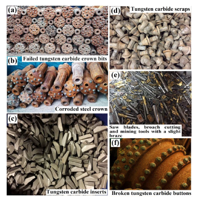
Figure 1 Digital image of different forms of cemented WC-Co scraps for recycling: (a) scraps of crown bits; (b) corroded steel crown; (c) WC inserts; (d) WC scraps; (e) scraps of saw blades, broach cuttings, and drilling tools with a slight braze; and (f) heavily damaged WC buttons scraps.
The digital image of the as-received WC-Co scrap materials used in the present study is shown in Fig. 2.
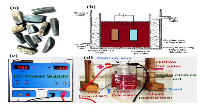
Figure 2 (a) Scraps of the cemented WC materials: the unwanted brazing material (golden-yellow) can be seen on its surface; (b) schematics of the electrochemical cell set up; (c) digital images of DC power supply; and (d) electrodissolution experiment cell set up equipped with a water recirculation system through annulus, for electrolyte cooling.
The cemented WC scrap sample contained 81.2% W, 5.2% C, 10.15% Co, 0.98% Fe, 0.062% Al and 0.005% Ti (all in wt.%). W, Co, and C are the major constituents in WC-Co. Impurities, such as Al, Ti and Mo, were present in trace amounts, including about 1.0% Fe.
The XRD pattern of the sample is shown in Fig. 3(e). The XRD peaks showed that the major phases were WC, Co6W6C and Co (JCPDS files: 25-1047, 23-0939 and 05-0727, respectively).
Chemicals
The NH3 electrolytes were prepared by proper dilution of an AR grade NH3 solution. All the dilutions were done using laboratory-grade deionized water processed by the Millipore Mili-Q system. The AR grade NH4Cl, (NH42)CO3 and (NH4)2SO4 were used as additives in the PDP and electrodissolution studies. All the abovementioned substances were procured from Merck Specialities Private Limited (Mumbai).
Electrodissolution methods
Initially, the WC-Co sample was subjected to PDP tests, so as to obtain an electrochemical response (dissolution and passivation), using a Gamry Echem Analyst potentiostat. WC-Co dissolution was subsequently studied by electrodissolution experiments, with the help of an electrolytic cell, by turning the sample into an anode in an electrochemical cell. A rectifier supplied the DC, procured from M/s Gayatri Enterprises, Pune. W and Co dissolved in the electrodissolution experiments were recovered by the precipitation method. Details of all the experimental procedures are given in the following sections.
PDP studies
A Gamry Echem Analyst potentiostat was used for PDP studies. A three electrode cell sell setup comprised WC-Co scraps, SC and a Pt foil, which were used as WE, RE and CE, respectively. The WE was connected, with the help of the Pt wire, to the power supply. The exposed surface area of the WC-Co sample was ~1cm2, and it was coated with the chemically inert resin. The sample was polished so as to produce a new mirror surface, with the help of different grits of emery paper and a polishing disc, and rinsed with deionized water, before each experiment. The working cell consisted of a 150 mL glass beaker containing 100 mL of an electrolyte solution, WE (WC-Co scraps) and CE. This cell was filled with fresh electrolytes for each PDP experiment. The SC RE was placed in another glass beaker (reference cell) containing a 100 mL saturated KCl solution. A salt bridge was used to connect both cells.
To prepare a salt bridge, 2.5 gm agar-agar were thoroughly mixed into a solution of 25 g KCl in 150 mL deionized water, and heated at 90 ºC. After mixing, the solution was partially cooled and sucked through one end of a ‘U’ shaped glass tube (salt bridge), until it reached the other end. The salt bridge was stored by dipping both ends in a saturated KCl solution in a glass beaker. During PDP studies, one end of the salt bridge was placed close to the WE, while the other was placed near the RE (17). In the PDP study, the applied E was increased with a programmed SR, while the current was continuously monitored. Then, J vs. applied E was drawn. Such as in a typical PDP scan, the initial and final E were set from -1.5 V to 7 V, with respect to the RE, at a SR of 1.5 mV/s. All the PDP experiments were carried out at room temperature. In some of them, the calculated quantity of a few chemicals was dissolved as an additive into the electrolyte, before the scan.
Electrodissolution studies
Electrodissolution experiments of the WC scraps were carried out in a 500 mL glass beaker cell. The cell, filled with 275 mL of electrolyte, was equipped with a water recirculation system, in order to cool the electrolytes during electrodissolution. WC scraps were connected to the Pt wire, and suspended in the electrolyte, as the anode. A 304 grade SS sheet was employed as cathode. Both anode and cathode were immersed into the electrolyte solution, and DC power was supplied by a rectifier manufactured by Gayatri Enterprises, Pune (model: Power Tron). In the electrodissolution experiments, the WC anode was connected to a positive power supply, and the negative power supply was connected to the SS cathode. In all the tests, there were efforts to control the cooling water temperature, by recirculation. During electrodissolution, the E (from 5 to 15 V) was applied by the rectifier, and the corresponding dissolution current was manually noted every 5 min, and the changes in temperature were measured by a thermometer.
Three sets of electrodissolution experiments were carried out, so as to obtain optimal conditions. In the first, different additives (NH4Cl, ((NH4)2SO4 and (NH4)2CO3) were taken (5% w/v) in 150 g/L NH3, at an applied potential of 10 V, to see their effect on J, and on W and Co recovery. The second set of experiments aimed to evaluate the impact of different NH3 concentrations (100, 150 and 200 g/L) in 5% NH4Cl, at an applied E of 10 V. The third set of experiments was run by varying the applied E (5, 10 and 15 V) and the additive concentrations (2, 5, 10 and 15% w/v) in a 150 g/L NH3 electrolyte.
It is worth mentioning that all the electrodissolution experiments were carried out during 2 h. After each investigation, the cathode and anode were rinsed in the deionized water, dried in the air for 1 h, and weighed in an electronic balance, so as to calculate the anodic dissolution and cathodic deposition percentages, using the following formulas:
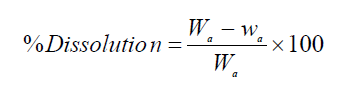 (1)
(1)
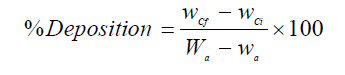 (2)
(2)
where Wa and wa are the weight (grams) of the anode (WC sample), before and after the experiment, respectively, and wCi and wCf are the initial and final weight (grams) of the cathode. After the experiments, the electrolyte was analyzed, in order to determine W and Co concentrations. It is worth mentioning that each electrochemical measurement was performed four times, so as to ensure the repeatability of the experiments.
Characterization
The distribution of the samples morphology and surface elements was studied by SEM (Hitachi-S3400N scanning electron microscope), coupled with EDX. XRD patterns of WC-Co scraps and obtained WO3 powder were recorded on a Siemens D500 X-ray diffractometer, using Ni filtered CuKα radiation (30 kVA, 15 mA), at a scanning speed of 2º(2θ)/min. The different phases were identified from the XRD pattern, with the help of JCPDS files.
Observation of the dissolved WC-Co scraps was also performed using AFM, so as to study the extent of the typical dissolution behaviour and explain its mechanisms, using the topographic image of the attacked surface, after the PDP and electrodissolution experiments. In order to study the surface characteristics, dissolved WC-Co samples were subjected to ultrasonic cleaning using acetone, for removing the loosely bounded undissolved and passivated materials from the anode surface. All the topographical studies were carried out in the contact mode, with asylum research AFM (MFP3D), at a SR of 0.5 Hz.
WO3 recovery from the electrolytic solution
After the WC-Co dissolution, the concentrations of W, Co and other elements were estimated by ICP-OES. The spectrometer was calibrated using different dilutions of an individual analyte standard solution procured from Merck, India. After that, the samples were run through a capillary into the ICP, so as to determine the emission, which was automatically processed by the spectrometer, giving a final concentration value of a particular analyte.
The electrolyte obtained after the optimum electrodissolution experiment was further processed, in order to recover dissolved W as YTO. 50 mL of concentrated HCl were added drop by drop to the electrolyte containing H8N2O4W (Fig. 13), by constant stirring it, which produced a white milky solution. After HCl addition, the white solution was heated at 50 ºC, for 1 h, for obtaining a yellow color precipitate of H2WO4 (Fig. 13(b)), which was separated by a centrifuge (5000 rpm). The yellow H2WO4 precipitate was heated for 1 h, at 900 ºC, in a muffle furnace, so as to obtain YTO, which was subjected to XRD analysis.
Results and discussions
WC-Co scraps characterization
The scraps chemical composition was: 81.2% W, 5.2% C, 10.15% Co, 0.98% Fe, 0.062% Al, and 0.005% Ti (all in wt.%). W, Co, and C were the principal constituents in the WC-Co tool bits. However, the impurities (Al, Ti and Mo) were also present in trace amounts, including about 1.0% Fe.
In order to remove the brazed material, WC-Co scraps were dipped into the aqua regia solution, for 4h, at 50 ºC. The samples were then cleaned, for performing the microstructural and XRD analyses. Fig. 3 (a) shows the micrographs of the WC-Co scraps in the BSE mode. Grey-colored fragmented WC grains were observed in the dark-colored Co matrix.
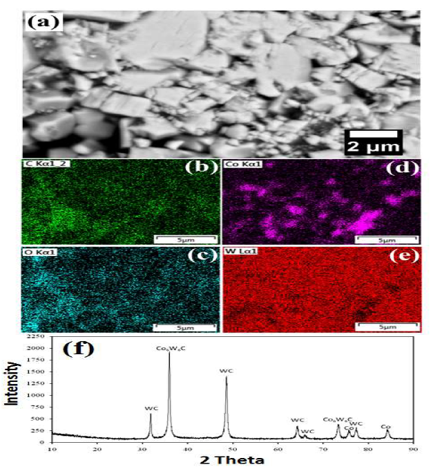
Figure 3 WC-Co scraps: (a) as-received microstructure; (b-d) mapping analysis after dissolution; and (e) XRD pattern.
The WC-Co tool bit was scrapped material obtained from mining sites. Since tool bits (as-received) faced extreme environmental conditions, fragmented WC grains were observed in the Co matrix. Different shapes and sizes and disintegrated small WC grains are shown in Fig 3(a).
Mapping results have confirmed the presence of various elements (O, C, W and Co) in the materials. The EDS map shows the homogeneous distribution of all the elements (Fig. 3(b-e)). The sample XRD pattern is shown in Fig. 3(f). XRD peaks showed that the major phases were WC (JCPDS file: 25-1047), Co6W6C (JCPDS file: 23-0939) and Co (JCPDS file: 05-0727).
PDP tests
The anode dissolution extent, its inherent mechanisms and passivation behavior can be well understood with the help of polarization tests, in terms of the OCP (Table 2) and J values (Fig. 4). The OCP value gives information about the thermodynamic stability or nature of the very thin passive film (EDL) formed at the WC-Co and NH3 solution interface. However, maximum anodic J and OCP higher negative values provide useful information about the active dissolution reaction, rather than about passivation. It is worth mentioning that the OCP value was obtained after 1 h of exposure tests (Table 2). Therefore, the EDL was formed at the electrode/electrolyte interface. Consequently, all samples have been polarized from the OCP value.
Table 2 Various electrochemical parameters obtained after PDP tests.
| NH3 solution | Additives types and amount | OCP | Maximum anodic J | Voltage corresponding to maximum anodic J |
| g/L | wt. % | mVSCE | mA/cm2 | VSCE |
| 50 | - | -824±12 | 20.30±0.35 | 2.50±0.047 |
| 100 | - | -854±07 | 25.80±0.46 | 2.50±0.027 |
| 150 | - | -884±16 | 32.80±0.15 | 2.50±0.044 |
| 150 | 1% (NH4)2CO3 | -719±12 | 294.40±0.62 | 4.78±0.035 |
| 150 | 1% (NH4)2SO4 | -779±11 | 352.40±0.83 | 3.43±0.047 |
| 150 | 1% NH4Cl | -795±14 | 543.70±0.082 | 2.47±0.093 |
| 150 | 5% NH4Cl | -659±08 | 819.10±0.063 | 2.03±0.038 |
| 150 | 10% NH4Cl | -644±07 | 819.10±0.045 | 1.98±0.063 |
The OCP values increased with higher NH3 solution concentrations (50, 100 and 150 g/L), because the tendency to dissolve WC-Co materials was higher in 150 g/L NH3. Also, the pseudo-passive plateau region (from -1 to 1 VSCE) has been observed for the 150 g/L NH3 solution, indicating an active dissolution tendency (Fig. 4(a)).
However, in the 50 and 100 g/L NH3 solution, a stable passive region could be seen in the same potential range (-1 to 1 VSCE), showing the regular passive tendency on the WC-Co electrode surface. The anodic J values of the 50 and 100 g/L NH3 solutions, at the same E range, were observed to be lower than that of the 150 g/L solution. This means that higher concentrations (150 g/L) of the NH3 solution inhibited the passivation tendency.
Maximum anodic J at minimum E is a favored condition to achieve higher anodic dissolution rates, which is only possible by avoiding the anode passivation, with a higher NH3 solution concentration (Fig. 4(a)).
Hence, maximum anodic current led to the maximum dissolution rate of WC-Co samples 17,38. However, the overall maximum anodic J was significantly lower in the NH3 solution without additives, and further increase in the E may have strengthen the anodic current. Still, it would consume more energy, and increase the probability of formation of a passive oxide layer on the electrode surface.
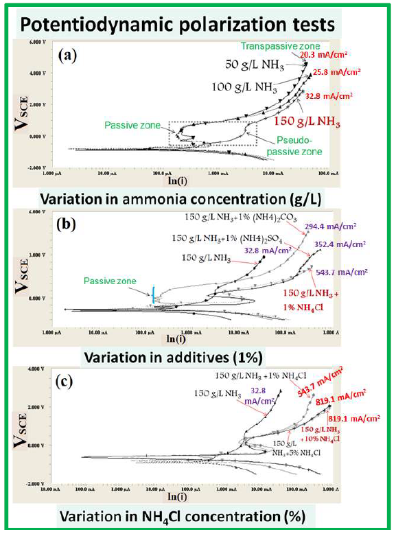
Figure 4 PDP tests of the WC-Co scraps in a freely aerated NH3 medium with different additives: (a) 50, 100 and 150 g/L NH3; (b) 150 g/L NH3 +1 % (NH4)2CO3, (NH4)2SO4, and NH4Cl; and (c) 150 g/L NH3 +1, 5 and 10% NH4Cl.
Therefore, the addition of chemical additives can avoid the formation of any passivation (Fig. 4(b)). Nevertheless, the NH3 solution was initially not enough conducting to conduct the dissolved ions fastly in between the electrode. Thus, the dissolution rate was found to be very low, due to decreased anodic J.
The addition of compounds, such as NH4Cl, (NH4)2SO4 and (NH4)2CO3, has not only contributed to increase the solution conductivity (by adding the additional ions), but has also avoid the possibility of any stable passive film formation on the WC-Co materials exposed surface (Fig. 4 (b and c)).
When it is likely that a stable passive layer is formed, the Cl- ions turn out to be highly aggressive, and penetrate through it, by attacking W and Co (which is responsible for local passivation), forming complex products and decreasing the possibility of the layer formation. Similarly, SO4 -2 and CO3 -2 have done the same thing, but they were less effective than Cl- ions 39.
Therefore, such additives (containing aggressive ions) decreased the possibility of a stable passive layer being formed, and the resultant maximum anodic dissolution current was obtained at minimum E (Table 2).
However, WC dissolution was still hindered by the same optimal concentration of 150 g/L NH3 solution, with 1% NH3 Cl additives (Fig. 4(b)). So, an increase in NH4Cl up to 10 %, in a 150 g/L NH3 solution, enhanced the anodic dissolution.
SO4 -2 and CO3 -2 have a similar behaviour, but they are less effective than the Cl- ions 39.
In summary, if the NH3 solution concentration increases from 50 to 150 g/L, the corresponding OCP value decreases. This means that the NH3 concentration makes the surface thermodynamically more active for dissolution, while the anodic current drops, because Co tries to passivate the surface in the absence of these aggressive ions, by forming a stable complex (Fig. 4(c)).
Furthermore, a more negative OCP value (Table 2) represents a higher tendency for WC dissolution in NH4OH. This indicates that NH3 concentrations can limit the anodic dissolution rate. However, the OCP values were still very low, even after the addition of 1% NH4Cl, (NH4)2SO4 and (NH4)2CO3. Moreover, OCP tended to shift towards the noble direction, with 1 to 10% NH 4Cl. It is interesting to note that this behavior was not maintained in the presence of Cl- ions (after the addition of 5 to 10% NH4Cl), which probably reduced the tendency for a passive layer being formed on the exposed surface. Thereby, a stronger dissolution tendency has been observed at higher concentrations (150 g/L NH3 with 10% NH4Cl) of Cl- ions, at minimum E.
Hence, it is inferred that the additives played a significant role in the WC materials de-passivation, and in the solution conductivity increase. However, W driving force and maximum solubility limit, in the NH3 solution fixed concentration, became a rate-limiting step for WC-Co dissolution. This could explain why OCP value has shifted towards a noble direction, even after the addition of 1% NH4Cl, (NH4)2SO4 and (NH4)2CO3, and an increase in the NH4Cl additives concentration, from 1 to 10%. Since the electrolyte volume (100 mL) was fixed in all polarization tests, the same J value (819.1 A/cm2) has been noticed at different NH4C concentrations (5 and 10 %). However, the applied E was lower (1.98 VSCE), in the case of 10% NH4Cl. Although the OCP value has shifted to a noble direction, WC-Co dissolution tendency could be strongly limited by the NH3 solution concentration (without agitation). Also, maximum J value has been similarly obtained, because Co could not form a passive film on the surface, due to a high concentration of Cl- ions (in both cases).
In general, W was more anodically active in the NH3 medium than Co. Thereby, the formation of a W-based passive layer is less probable than that of Co, with higher NH3 concentrations. Hence, once the maximum Cl- ions concentration was reached (in the same volume of the NH3 solution), Co also ceased being able to form a passive layer, due to their aggressive nature. Therefore, the anodic J value has reached its maximum value at the minimum E.
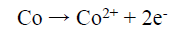
During the electrodissolution experiments, the WC-Co dissolution progressed, by forming WO4 2− and Co2+. However, W standard dissolution or oxidation E (0.09 V) was lower than that of Co (0.28 V). Hence, W tended to dissolve first, forming WO4 2− ions. And then, the anode became passivated when E reached a higher value, due to Co dissolution and formation of a passive layer 40. Therefore, W formed WO4 2−, through the anodic oxidation reaction in the NH3 solution, or due to the NaOH solution high pH (~11). Further, WO4 2− reacted with NH4 +, which is the soluble product, and the following chemical reaction can be expected 39,40.
 (3)
(3)
 (4)
(4)
The formation of WO4 2- was thermodynamically more feasible with a higher NH3 concentration (150 g/L), at a given E range. Hence, this reaction moved forward, and became more thermodynamically active when the NH3 content increased.
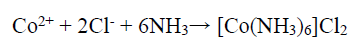
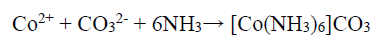
On the other hand, the Co binder anodic dissolution also occurred through the oxidation reaction, by forming Co2+. However, these tended to form a Co-based amine complex. Co has a higher tendency to form an octahedral amine-based complex ((Co(NH3)6 )+2), at a high dissolution E (0.28 V), in which NH3 acts as a ligand, and the following reaction can be expected 41:
 (5)
(5)
 (6)
(6)
Although Co2+ can be passivated by forming Co-hydroxides, which hinders further oxidation, this reaction depends on the NH4OH concentration that WO4 2- ions can also consume, and the following reaction is expected to occur:
 (7)
(7)
This concentration (150 g/L) and the NH3 solution pH (~11) significantly affected the WC-Co surfaces dissolution and passivation tendency. However, the Co+2 oxidation E was very high (0.28 V). Hence, at higher E and pH values, (Co(NH3)6 )+2 complex became more stable than Co3+, which is also relatively stable at lower pH values 41. Hence, at higher E and low pH (~ 7) values, Co+2 ions also oxidized into the very low oxidation E of Co+3 ions (-1.82 V), forming the unstable amine-based complex (Co(NH3)6 )+3 (39.
150 g/L NH3 with the aggressive anions Cl-, SO4 2- and CO3 2- (separately obtained in the presence of NH4Cl, (NH4)2SO4, and (NH4)2CO3,) have significantly influenced the abovementioned reaction, by avoiding the stable Co passive layer formation. Therefore, enhanced anodic current was due to the higher anodic dissolution, by the formation of (Co(NH3)6 )Cl2, (Co(NH3)6 )SO4 and (Co(NH3)6 )CO3 complexes, and the following chemical reaction can be expected 39.
 (8)
(8)
 (9)
(9)
 (10)
(10)
WC-Co dissolution mechanisms
After the PDP tests, the AFM micrographs were used to obtain the dissolution behavior of the polarized WC-Co surface, which was caused by the aggressiveness of the different concentrations of NH3 electrolytes with various additives. The AFM topographical micrographs from the corroded WC-Co surface helped to examine the anode materials dissolution tendency, based on the average Ra. The dissolution intensity, which is a localized attack on the polarized surface, can vary accordingly to different conditions, which depend on the ions (Cl-, SO4 -2 and CO3 -2) aggressiveness, and on the correspondingly obtained maximum anodic J. Hence, the attacked surface was evaluated after the PDP tests, in terms of the average Ra value Fig. 5 shows the WC-Co anode topographical image, after electrochemical dissolution tests in a freely aerated 150g/L NH3 solution with 1% (NH4)2CO3.
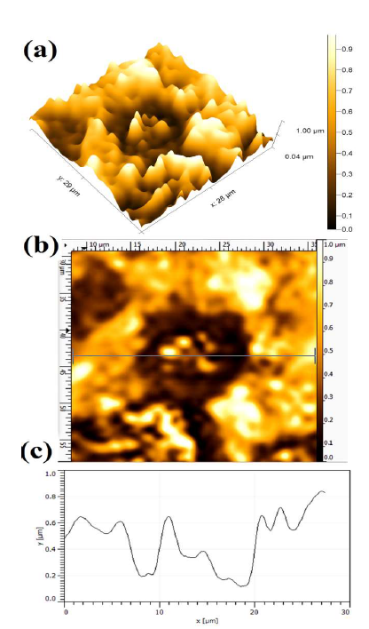
Figure 5 Topographical image of WC-Co anode, after PDP tests, in a freely aerated 150 g/L NH3 solution with 1% (NH4)2CO3.
A more severe dissolution can be seen at the WC grains and Co matrix interface. Since the WC grains are nobler than the Co matrix, maximum dissolution can be seen in the binder phase (Co) regions. The dissolution differential that occurs between the WC grains and the Co electrode is due to their different E values, which lead to the cathode and anode formation. Hence, the dissolution behavior is mainly influenced by the formation of galvanic couples between the WC grains noble cathode and the Co phase active anode 2,42. The average Ra value was 0.387 ± 0.017µm, in the presence of (NH4)2CO3 additives.
Fig. 6 shows the WC-Co anode topographical image, after the electrochemical dissolution tests, in a freely aerated 150g/L NH3 solution with 1% (NH4)2SO4. The average Ra was obtained at 0.503 ± 0.013µm. However, the dissolution behavior was identical.
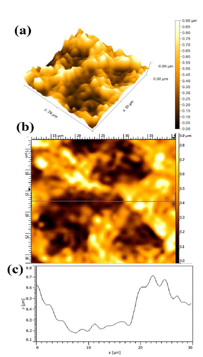
Figure 6 Topographical image of WC-Co anode, after PDP tests, in a freely aerated 150 g/L NH3 solution with 1% (NH4)2SO4.
Fig. 7 shows the WC-Co anode topographical image, after electrochemical dissolution tests, in a freely aerated 150g/L NH3 solution with 1% NH4Cl. The lowest (0.387 ± 0.017µm), intermediate (0.503 ± 0.013µm) and highest (0.704 µm ± 0.083µm) Ra values were obtained with 1% each (NH4)2CO3, NH4Cl and (NH4)2SO4, respectively.
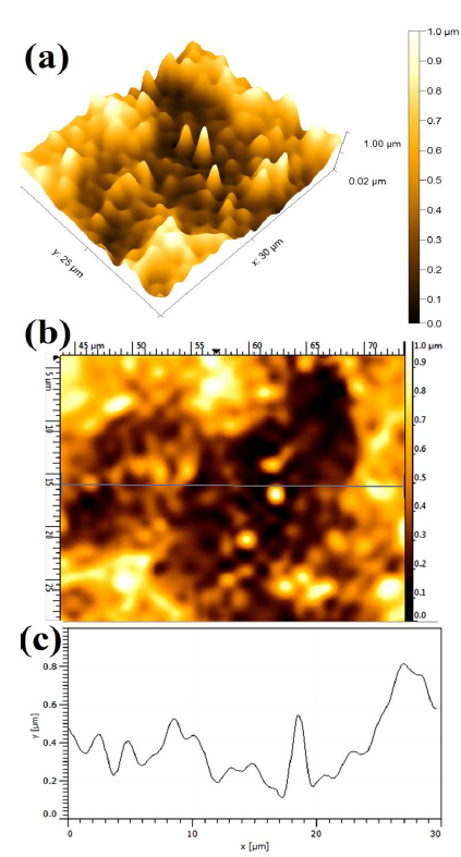
Figure 7 Topographical image of WC-Co anode, after PDP tests, in a freely aerated 150 g/L NH3 solution with 1% NH4Cl.
Fig. 8 shows the polarized WC-Co anode topographical image in a 150 g/L NH3 solution with 5% NH4Cl. Since the maximum dissolution current was observed in the presence of 5% NH4Cl additives, it can be seen in terms of the average Ra value (0.842 µm ± 0.051µm). The stronger attack led to WC-Co maximum dissolution depth, which resulted in a rougher surface, and in its limited tendency to form an adherent or protective layer on the anode surface. In fact, the formation of a stable passive layer can reduce the dissolution attack, in the presence of (NH4)2CO3 and (NH4)2SO4 additives. Therefore, the anode susceptibility to dissolution, with different additives in the NH3 solution, is strongly influenced by the obtained maximum anodic J and the presence of different ions.
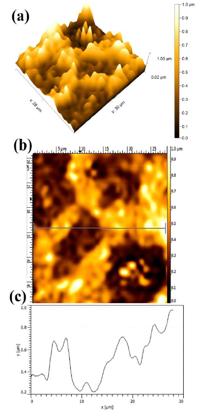
Figure 8 Topographical image of WC-Co anode, after PDP tests, in a freely aerated 150 g/L NH3 solution with 5% NH4Cl.
WC-Co electrodissolution tendency
Combined effect of NH 3 and additive concentrations
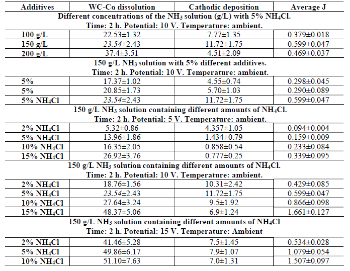
It is worth mentioning that the time of all the electrodissolution experiments was exactly 2 h, and the electrolyte was at ambient temperature. Co cathodic deposition, and the average anodic J obtained after the WC-Co scraps dissolution in freely aerated solutions, using different parameters, are given in Table 3.
Table 3 Co cathodic deposition and average J obtained after WC-Co scraps dissolution in freely aerated solutions, using different parameters.
However, electrodissolution studies in the NH3 medium without additive were not carried out, since PDP studies without an additive gave rise to a much weaker anodic current. Therefore, a study in the NH3 medium (150 to 200 g/L) with 5% NH4Cl additives was performed, to ensure the active dissolution and the deposition effect with the solution higher concentrations.
It can be seen, from Fig. 9(a), that the anodic dissolution that was achieved at a NH3 concentration of 200 g/L, was the highest, while the cathodic one was the lowest. This was perhaps because some loosened anode material, caused by Co partial dissolution, settled at the bottom of the electrolyte without being dissolved (later, it could be recovered by electrowinning methods). However, the highest J value was achieved with a 150 g/L NH3 solution. Thus, this NH3 concentration with 5% NH4Cl was considered an optimum condition, and further experiments were carried out with this parameter. Fig. 9(b) also shows the correlation among the anode material (WC-Co tool bits) dissolution (%), Co deposition (%) at the cathode and average J, achieved by the electrodissolution experiments, in the 150 g/L NH3 solution with 5% each of (NH4)2CO3, (NH4)2SO4 and NH4Cl, at 10 V. Those parameters achieved their maximum values with 5% each NH4Cl, followed by (NH4)2SO4 and (NH4)2CO3. The highest cathodic deposition (11.72%) and the maximum average J (0.5995 A/cm2) were observed, because Cl- ions accelerated the dissolution rate, by avoiding the passivation in the 150 g/L NH3 electrolyte with 5% NH4Cl. Therefore, it was found that NH4Cl was the best option, and, hence, further experiments in the NH3 medium were carried out only with this additive.
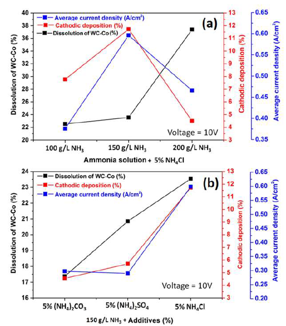
Figure 9 Correlation between the WC-Co scraps dissolution (%), Co cathodic deposition (%) and average J with: (a) different NH3 concentrations (100, 150 and 200 g/L) with 5% NH4Cl, at 10 V, at ambient temperature, for 2 h; and (b) with 5% of different additives ((NH4)2CO3, (NH4)2SO4, and NH4Cl) in a 150g/L NH3 solution, at 10 V, at ambient temperature, for 2 h.
During the studies on the NH3 concentration effect on the WC-Co tool bits electrodissolution, it was observed that some Cl evolution took place at the cathode, with the NH3 lower concentrations (50 and 100 g/L), which may have influenced Co deposition behavior on the SS cathode. At higher NH3 concentrations (150 and 200 g/L), no Cl evolution was observed. It seems that, with higher NH3 concentrations, whatever Cl amount was evolved at the anode, in NH4Cl electrolysis, got converted to HCl, which reacted with NH3, producing NH4Cl 43.
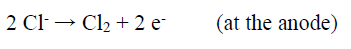 (11)
(11)
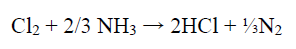 (12)
(12)
 (13)
(13)
NH 4 Cl and impressed voltage synergistic effect
The effect of varied (2, 5, 10 and 15%) NH4Cl amounts, in the 150 g/L NH3 electrolyte, on the WC-Co tool bits electrodissolution, at 5, 10 and 15 V, is shown in Fig. 10 (a), (b) and (c), respectively. It can be seen that the electrodissolution was stronger as the NH4Cl amount increased from 2% to 15%.
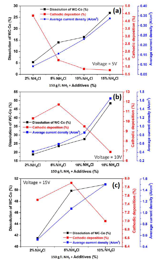
Figure 10 Correlation between WC-Co scraps dissolution, Co cathodic deposition (%) and average J, with 2, 5, 10 and 15 % NH4Cl additives in a 150g/L NH3 solution, at operating voltages of: (a) 5 V; (b) 10 V; and (c) 15 V, at ambient temperature, for 2 h.
Fig. 10 (a) shows the correlation among the WC-Co scraps dissolution (%), Co cathodic deposition (%) and average J values, with NH4Cl different concentrations (%) in a 150g/L NH3 solution, at an operating voltage of 5 V, at ambient temperature. It can be seen that the average J values increased with higher NH4Cl amounts.
Additionally, the NH3 electrolyte became more conductive with higher levels of Cl- ions. The maximum dissolution achieved by the WC-Co tool bits was 26.92%, with 15% NH4Cl, because the average anodic J increased with higher contents of this additive, from 2 to 15%, at 5 V.
The cathodic deposition values in these experiments are also plotted in Fig. 10(a), which shows that it decreased with higher additive amounts, reaching its maximum (4.36%) with 2% NH4Cl.
The average J values with NH4Cl different amounts, at 10 V, are plotted in Fig. 10(b). They were much higher at 10 V than at 5 V. Maximum J, with 15% of the additive, was 1.66 A/cm2, at 10 V, while, at 5 V, it was 0.34 A/cm2.
The effect of NH4Cl addition, at this higher voltage, on the WC-Co tool bits dissolution (%) is shown in Fig. 10(b). It was seen that the anodic dissolution was stronger with increasing additive percentages, and maximum dissolution (48.3%) was obtained with 15% NH4Cl.
It was observed that the maximum cathodic deposition (11.72%) was obtained with 5% of NH4Cl, and, with higher percentages, it drastically decreased (Fig. 10 (b and c)), due to the formation of Cl2 gas bubbles near the cathode.
The electrodissolution studies were carried out at higher voltage (15 V), with 2, 5 and 10% NH4Cl. It can be seen, from Fig. 10(c), that the WC-Co tool bits anodic dissolution increased with higher NH4Cl amounts. About 50% of the anode dissolution occurred with 5% NH4Cl. With 10% NH4Cl, the dissolution was just 51%. Therefore, experiments with higher NH4Cl amounts were not carried out. The cathodic deposition values with different percentages of the additive, in the electrodissolution experiment, at 15 V, are shown in Fig. 10 (c). Here, the maximum cathodic deposition was achieved with 5% NH4Cl. It is worth mentioning that the increase in voltage (10 to 15 V) with higher NH4Cl percentages (10 to 15%) led to stronger anodic currents that caused the anode decomposition and fragmentation. Hence, less Co dissolution in an electrolyte may lead to lower deposition.
Fig. 11 shows that the average J values and corresponding WC-Co scrap dissolution increased at higher operating voltages, with concentrations of 2, 5 and 10% NH4Cl. However, the cathodic deposition reached its maximum at 10 V, with those concentrations of the additive. Therefore, 5% NH4Cl in the 150 g/L NH3 solution, at 10 V, was an optimum parameter for WC-Co scraps dissolution (%), Co deposition on the cathode surface and average maximum J.
It is worth mentioning that all the electrodissolution studies have been carried out for two hours, and it is expected that, with a longer duration of the experiment, higher recovery could be achieved.
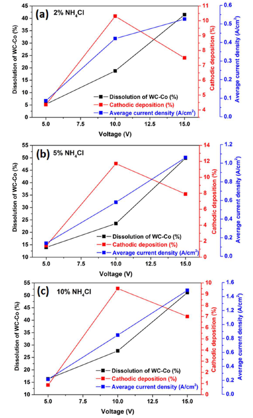
Figure 11 Correlation between WC-Co scraps dissolution (%), Co cathodic deposition (%) and average J with: (a) 2%; (b) 5%; and (c) 10% of NH4Cl in a 150g/L NH3 solution, at different operating voltages of 5, 10 and 15 V, at ambient temperature, for 2h.
Dissolved WC-Co surface morphology
Resuming, the optimum parameter for the stronger WC-Co scraps dissolution (%) and average maximum J was found to be with 15 % NH4Cl in the 150 g/L NH3 solution, at 10 V. The extent of WC-Co dissolution can be clearly observed by AFM micrographs. Fig. 7 shows the WC-Co anode materials topographical image after the electrochemical dissolution tests, in a freely aerated 150 g/L NH3 solution with 15% NH4Cl. The maximum average Ra value (1.82 ±0.085 μm) was obtained. It is worth mentioning that, before the AFM analysis, the WC-Co remaining anode, obtained after electrodissolution, was subjected to 20 min of ultrasonic cleaning, in an acetone medium, so as to remove its loosely bounded residues, and enhance the surface topography image.
Fig. 12 (a) shows the number of WC grains that were dissolved or coming out from the matrix. However, the dissolution could have started in the WC grains and Co interface. However, undissolved WC grains could also be seen after the Co phase dissolution.
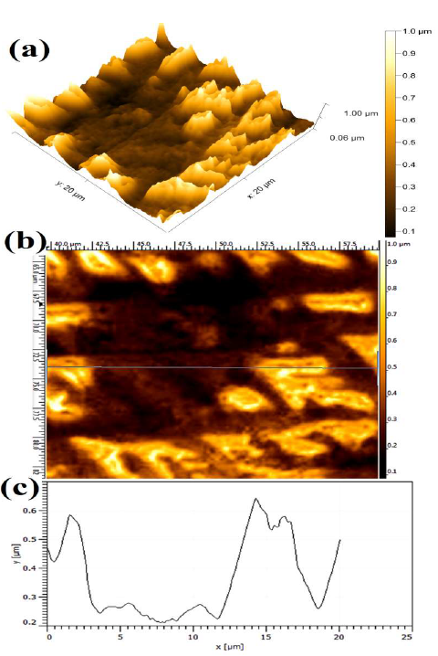
Figure 12 Topographical image of WC-Co anode, after electrochemical dissolution tests, in a freely aerated 150g/L NH3 solution with 15% NH4Cl, at 10 V.
W recovery from the electrolytic solution
W recovery in the electrodissolution experiments was calculated based on the anode chemical analysis and the metal dissolved in the electrolyte. The recovery values, at 5 V, with different NH4Cl percentages, are given in Table 4. It can be seen that W recovery increased with higher NH4Cl percentages, reaching a maximum value of 37.51% with 15% NH4Cl. At 10 V, W recovery also increased with higher NH4Cl percentages in the 150 g/L NH3 electrolytes, reaching a maximum value of 65.26% with 15% NH4Cl.
Table 4 W recovery in the electrolyte, after the electrodissolution experiments.
| Applied voltage (V) | 150 g/L NH 3 solution + % additives | |||
| 2% NH 4 Cl | 5% NH 4 Cl | 10% NH 4 Cl | 15% NH 4 Cl | |
| 5 | 8.69±1.31 | 20.82±2.42 | 23.62±2.43 | 37.51±3.76 |
| 10 | 17.92±1.86 | 25.31±1.86 | 35.45±1.45 | 65.26±7.63 |
| 15 | 61.10±4.28 | 69.72±6.06 | 68.53±5.28 | - |
With different concentrations of NH4Cl in 150 g/L NH3 electrolytes, W recovery in the electrodissolution was quite high, at 15 V. It was 61.10% with 2% NH4Cl, and it increased to 69.72% with 5% NH4Cl. With 10% NH4Cl, there was no significant change in W recovery (65.53%). Since W recovery with 5 and 10% NH4Cl was almost the same, no further experiments with higher amounts of the additive were made.
Although the highest W recovery in the electrodissolution study was obtained with 5% NH4Cl, at 15 V, the electrolyte temperature increased more (75 oC) than at 10 V (45 oC). It may be noted that the experiments at 10 V yielded 65.1% of W recovery, with 15% NH4Cl, which was very near to its highest amount (69.72%), at 15 V. However, since the electrodissolution at 10 V consumed less energy than at 15 V, it seems that the optimal parameters for WC-CO tool bits electrodissolution, were 10 V and 15% NH4Cl in 150 g/L NH3. W recovery in the electrolyte solution was 65.1%, for 2 h, and it was further treated to produce saleable YTO.
Products characterization
After the electrodissolution experiments, the NH3 electrolyte containing W, as H8N2O4W, was acidified with HCl and heated, for 1 h, at 50 ºC. The precipitated H2WO4 was separated by centrifugation, and heated at 900 ºC, to obtain YTO. An image of YTO prepared from WC-Co scraps is shown in Fig. 13.
Fig. 13(a) shows the H8N2O4W solution obtained after the electrodissolution tests. Fig. 13(b) shows the precipitated H2WO4 obtained after the H8N2O4W solution acidification. The acidification with HCl was followed by mild heating at 50 ºC, for 1 h. Fig. 13(c) shows the YTO powder produced from the precipitated H2WO4 that was obtained after centrifugation, followed by heating at 900 ºC, in a tube furnace. The purity of W and Co recovered from the WC-Co scraps was also a significant concern of the present study. Hence, YTO powder was also compared to the standard WO3 XRD pattern, as shown in Fig. 13(d). The XRD pattern of the YTO prepared in the present work matched well with the standard WO3 JCPDS pattern (43-1035) shown in Fig. 13(e), which confirmed the nature of the product. Co deposited on the cathode was manually separated and washed with deionized water, for the XRD characterization. A SEM image of Co cathodic deposition (inset of Fig. 13(f)), in the form of separated chips, and the corresponding EDS spectra, are shown in Fig. 13(f) and (g), respectively.
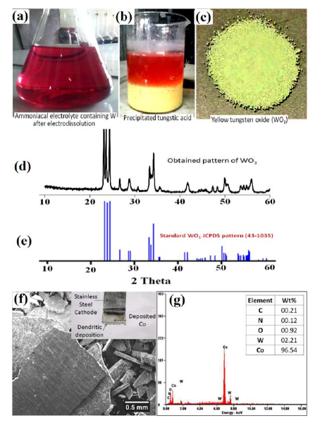
Figure 13 (a) Electrolyte after electrodissolution tests (pink colored H8N2O4W solution); (b) precipitated H2WO4; (c) YTO; (d) XRD pattern of YTO prepared in the present work; (e) YTO XRD pattern compared with that of JCPDS (43-1035); (f) SEM image of the deposited Co cathode after WC-Co scrap samples electrodissolution; and (g) EDS pattern of the deposited Co cathode.
In the present paper, PDP studies on WC-Co scraps have been carried out, since they reveal better their anodic dissolution behavior, in order to recover those metal values. PDP studies also provided information on suitable electrolytes, and found out the maximum anodic current at selective electrolytes, with or without additives. The maximum anodic current produced the WC-Co scraps stronger dissolution, without any passivation. During the electrodissolution experiments, it was initially found that the anodic current was very high, and, after some time, it continuously decreased, causing a reduction in the anode dissolution. This phenomenon is called passivation, and it occurred due to the formation of the anode passive layer. However, it was seen that the anodic passivation retarded the scraps dissolution, and adversely affected the metals recovery. So, in order to minimize the passivity and increase the anodic dissolution, some chemicals were used as additives. NH4Cl, (NH4)2CO3 and (NH4)2SO4 were added in different concentrations to the NH3 electrolyte. The studies revealed that 5% NH4Cl were suitable for obtaining the maximum anodic dissolution (current) in 150 g/L NH3. Therefore, the WC-Co tool bits electrodissolution in NH3 effectively dissolved both W, as H8N2O4W, and Co, as a Co-amine complex. Further, Co was deposited at the cathode during the electrolysis, while H8N2O4W remained in the electrolyte, from where W could be recovered as H2WO4 or WO3.
Therefore, WC-Co scrap produced by the mining industries was electrochemically dissolved, producing H8N2O4W, and Co collected from the cathode. H8N2O4W was converted into APT crystal, by filtering and evaporating it into white APT. On the other hand, H8N2O4W electrolytes could be converted into W acid, by neutralization, using HCl, and later, they could be recovered in the form of YTO. Hence, the present recycling technique has more advantages than those from the reported recycling techniques, such as single-step direct processes, high purity saleable products (APT, WO3 and Co), low energy consumption and low cost environmentally friendly recycling methods.
Process flowsheet
Based on the electrodissolution studies, a flowsheet was proposed and illustrated (Fig. 14), for explaining the unit operations.
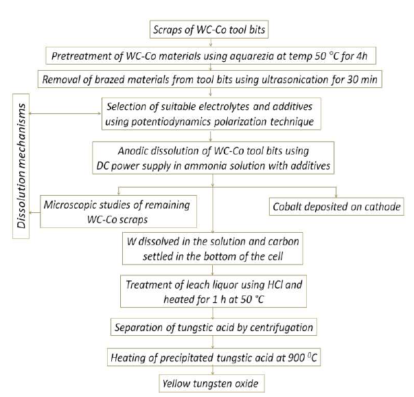
Figure 14 Flow chart for WC scraps recycling through electrodissolution routes, and the recovery of saleable APT and WO3, along with cathodically deposited Co.
For example, Co further treatment by electrorefining may increase its purity. The newly developed methods for recycling WC-Co scraps through electrodissolution routes, and recovering saleable APT and WO3 very pure, along with cathodically deposited Co, have an advantage compared to conventional processes, such as energy-intensive oxidation for eliminating WC-Co, since they have just a few industrial requirements, limited processing steps, recovered saleable products in simple unit operations, etc. 38.
Conclusions
The WC-Co scraps used for the electrodissolution studies contained about 81% W, 10% Co and 5% C, apart from the minor amounts of Fe, Al and Ti. The XRD analysis showed that W was mainly in the WC phase, and Co in the metallic form.
The initial polarization studies demonstrated that, without additives in the NH3 electrolyte, the anodic J was not very high, but it increased significantly with NH4Cl, (NH4)2SO4 or (NH4)2CO3 addition, being the strongest with NH4Cl increasing amounts.
WC-Co scraps dissolution in a NH3 solution was found to follow the pitting corrosion mechanism, as it was evident from the AFM topographical images.
In the electrodissolution studies, it was seen that WC-Co anodic dissolution and J values were enhanced with higher NH4Cl contents, stronger voltage and increasing NH3 concentrations. The cathodic deposition achieved its maximum at 10 V, with 5% NH4Cl in 150 g/L NH3.
With the abovementioned optimum electrodissolution parameters in NH3 electrolytes, W recovery was 65.1%, in the 2h experiment. The W in the solution was further treated for producing YTO.
Acknowledgments
The authors are thankful to Dr. R. K. Jana (CSIR-NML), for its help in the PDP experiments. The authors thank the Director (CSIR-NML, Jamshedpur), for his permission to publish this work.
Authors’ contributions
Prvan Kumar Katiyar: performed the experiments as per the plan; acquired the necessary data and made the graphical formatting; performed the analysis on literature relevant to the studies; prepared the manuscript and structure in the style of journal article; collected relevant references. Navneet Singh Randhawa: conceived building and hypothesis testing; planned the experiments and selected parameters for the studies; analyzed the information collected from the experiments and selected useful data for testing the hypothesis; made the graphical and pictorial representation of the results; interpreted the experimental data for the results and discussion; made the final correction and formatting of the manuscript; acted as corresponding author and as resource person for all the requirements of the present study.
Abbreviations
AFM: atomic force microscopy
APT: ammonium paratungstate
Aqua regia: one part of concentrated HNO3 mixed with three parts of concentrated HCl
AR: analytical reagents
BCC: body-centered cubic
BSE: backscattered electron image
Co2+: cobalt divalent cation
CO3 -2: carbonate ions
Co6W6C: ternary carbide
DC: direct current
E: potential
EDL: electrical double layer
EDX: energy dispersive X-ray
H2SO4: sulfuric acid
H2WO4: tungstic acid
H3PO4: phosphoric acid
H8N2O4W: ammonium tungstate
HCl: hydrochloric acid
HCP: hexagonal close-packed
HNO3: nitric acid
ICP-OES: inductively coupled plasma - optical emission spectrometer
J: current density
JCPDS: currently known as ICDD (International Centre for Diffraction Data)
K α : x-rays produced by transitions from the n=2 to n=1 levels
KCl: potassium chloride
Na2WO4: sodium tungstate
NaOH: sodium hydroxide
NH3: ammonia
NH4Cl: ammonium chloride
(NH4)2CO3: ammonium carbonate
(NH4)2SO4: ammonium sulfate
NH4OH: ammonium hydroxide
OCP: open circuit potential
PDP: potentiodynamic polarization
Ra: average surface roughness
RE: reference electrode
SC: saturated calomel
SO4 -2: sulfate ions
SR: scan rate
SEM: scanning electron microscopy
ST: stainless steel
W: tungsten
WC-Co: tungsten carbide cobalt-bonded
WE: working electrode
WO3: tungsten oxide
WO4 2: tungstate ions
XRD: X-ray diffraction
YTO: yellow tungsten oxide

