


 Inglês (pdf)
 Artigo em XML
 Referências do artigo
 Enviar este artigo por email
 Citado por SciELO
  Similares em
SciELO
Similares em
SciELO 
 Permalink
Introduction
For many years, studies have shown that the industrial concerns on engineering components in service have been increasing. Zn coatings have been used to control MS corrosion, due to their better performance concerning deterioration resistance, ease of production, affordability and ability to overcome weak welds 1. The most widely utilized coatings contain Zn and its alloys as a reinforcement, because of their active nature, and unique protection given to the base metal 2. Due to Zn exclusive properties, such as its ability to withstand electrochemical deterioration in industrial and marine environments, it has been used in the production of components and structures. So as to produce stronger Zn-based coatings with a consistent structure, resistance and restricted surface imperfections for use in challenging situations, more chemically unstable metals, such as Al, Ni, Cu, Co, Mg and Mn, have been incorporated into them 3. NC Zn alloyed coatings, most especially with Ni-based materials, have more interesting applications for solid crystal structures than those of the unalloyed ones 4. Besides, alloying Zn with metals that contain Ni enhances their mechanical responses, while the coatings produced with NC materials give them excellent lubricating and tribological properties, which enable them to be widely used in different applications 5.
Furthermore, the majority of researchers suggested that hard Cr could be a possible alternative compound, with the inclusion of thermal sprayed, vapor-deposited and electroless Ni-P CC 6. Although all competing coating technologies offer some vital advantages, they still have a limited scope of usage if they present lack of vapor deposition, interchange in heat-treatment hardening towards disintegration, and are unable to offer quality protection against deterioration 7. Coated materials produced by several metals or alloys deposition techniques on a conducting surface, using the ED method, have become the most widely used. This is due to their ability for minimizing the waste rate associated with MS, through applications at different T ranges, so as to create an even surface that will improve boundaries and surface flow performance 8. Furthermore, ED is widely regarded as the best technique, due to its superiority in the fabrication of NC materials and metallic structures 9.
In order to synthetize a NC coating of good quality, the use of additives in electrolytic baths is crucial, since metals dissolution is only recognized at the atoms surface active sites with a weak bond. Therefore, the number of these sites requires that the surface nanometer scale and size range from 10 to 100 nm 10. These facts explain why metalloids, such as B, P and Fe, are the most common elements for Ni-based alloys coatings, of which purpose is to ensure their improved behavior and optimized protection of MS, compared to local coating materials that have reached an elastic limit of performance 2.
For these reasons, Zn-Ni alloy coatings are recognized as being more resistant to deterioration, with improved mechanical properties in aqueous solutions, while metal oxides, such as Al2O3 and TiO2, have been utilized as bath additives for enhancing NC materials 11. Therefore, it has become more attractive to develop Ni-Zn alloyed with metalloids and Al2O3 NC CC, using functional variables, such as DT, bath particle infringement concentration, pH, T, I and bath agitation speed on MS substrates 12.
Materials and methods
Metal specimen and preparations
A Zn anode with 99.9% composition of Z salts, Ni, P, Al2O3 and other materials, was sourced from an open laboratory in Lagos. MS contained 97.70% Fe and 0.134% C. The MS substrate was further partitioned, with the dimensions of 30 x 20 x 2 mm, and prepared according to ASTM standard. As in the study done by 4,13, with the aim to achieve a protected and structured surface, the electroplating apparatus was setup for the coating deposition. The bath comprised four stages with significant impact on the coating quality: cleaning, rinsing, pickling and plating. The deposition set contained discharging (anode) and receiving (cathode) terminals, which were attached to the rectifier, in order to control the E/I time input. Before using Na2CO3, the substrate surface was cleaned with fine grades of emery paper, in order to be smooth, and then it was pickled and activated with 5% HCl, at ambient T, for 10 s. Finally, it was rinsed with deionized H2O. The aqueous solution was made up of NiSO4.6H2O, ZnSO₄, NaPO2H2, C6H5Na3O7.2H2O, (NH4)2SO4, H3BO3, thiourea, glycine and Al2O314. The distance between cathode and anode was kept at 30 mm, with an electrode immersion depth maintained at 70 mm, while the samples were plated at different intervals of 15, 20, 25 and 30 min, with different J, at a T of 95 ºC. All the experiments were carried out under ambient conditions, at a speed of 300 rpm. The samples were rinsed in distilled H2O, for 5 s, in order to wash off the salt solution immediately after plating and, later, air dried, for characterization. The formulated design plan for the coating is described in Table 1.
Table 1 Formulated bath composition for Ni-Zn-P-15Al2O3.
| Matrix | DT (min) | J (A/cm2) |
|---|---|---|
| Ni-Zn-P-15Al2O3 | 15, 20, 25 and 30 | 1.5 |
After deposition, the structural properties were examined with a TESCAN SME equipped with EDS, for ascertaining the crystals elemental composition. The diamond base HVN tester used to examine the coated materials, for 10 s, contained a Vickers indentation, with a loading force of 20 g. The final value for the coatings ( was estimated as the average of 15 taken measurements. An autolab model (AuT101 and PGSTAT 30), controlled by a computer, was utilized to plot the polarization curve, and also to determine the sample CR/Ecorr rate. A reciprocating CETR UMT-2 tribometer was used to determine the wear behavior of the produced coating, at a T of 25 ºC. For this experiment, a coated MS substrate was cut, while an Al ball of 10 mm diameter was engaged as counter face, under a load of 5 N, at constant speed, displacement of 2000 m, oscillating frequency of 5 Hz and wear stroke length of 2000 m, for 20 min. The dimensions of the wear sample were 2 x 1.5 cm, in accordance with its holder. The average wear depths of the coated samples were used to evaluate the wear behavior.
Results and discussion
Structural effect on the alloy deposition
Figs. 1 and 2 show SEM/EDS analyses of Ni-Zn-P-15Al2O3 coated samples, at 15 and 30 min DT.
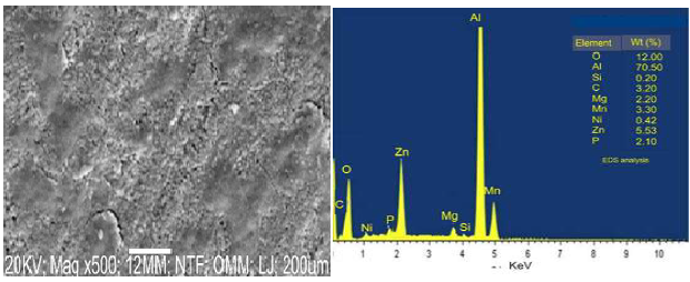
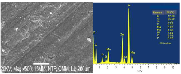
The coating surface, at 15 min DT, presented a coarse grain structure with holes and cracks, which might lead to the formation of degradation sites where the particles would be exposed to corrosive environments. At 30 min DT, the coating showed scattered small grains of white crystal with a uniform distribution. This fine grain structure of the coating was due to DT impact on Al2O3 reinforced NP in the matrix, which caused an increase in the nucleation site, and crystals growth (Fig. 1). Thus, one can conclude that the change in the coating structural morphology also resulted from its elemental composition, especially with the orientation of the composite seen in Fig. 2. Furthermore, an improvement in the sample surface, at 30 min DT, made the CC to firmly bond with the MS surface.
EDS analyses shown in Figs. 1 and 2 were used to determine the alloys elemental deposits. The CC was made of: at 15 min DT, O (12%), Al (70.50%), Ni (0.42%), Z (5.53%) and P (2.10%); and at 30 min, O (12%), Al (65%), Ni (1.52%), Z (6.53%) and P (3.20%). Comparing both, a difference of 1.10% in the weight increase was observed for Ni, Z and P, at 30 min, which indicates the significant impact of the three elements in the alloy structure (Fig. 2).
When examining the deposited sample and its composition, it is very clear that an increase in the Ni ions weight (%) contributed to a decrease in the coating porosity. This is because Ni ions filled pore spaces at 15 min DT. Generally, the deposited coatings, at 30 min, showed better grain structure than that of those at 15 min. Furthermore, an increase in J during EDS resulted in a smaller grain structure of the coating deposited for 30 min. There is indeed a clear difference between the coatings EDS at 15 and at 30 min DT. The EDS coatings at 15 min DT revealed Al, Zn, O and Mn peaks, while those at 30 min showed Al, Zn, O and C peaks.
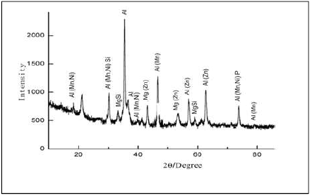
X-RD analyses
X-RD analyses of the deposited samples used in the study are presented in Figs. 3 and 4. The obtained result was derived at 2 degrees. Al showed the highest diffracted peak, at a position of about 38 degrees, with an intensity higher than 2000, at 15 min, while a position of 37 degrees, with more than 2000 counts, was observed at 30 min. The major diffracted peaks for the deposited samples appeared from 19 to 82 degrees, at 15 min, and from 21 to 79 degrees, at 30 min. At 15 min DT, three intermetallic phases were observed: Al(Mn, Ni)Si; MgSi and Al(Mn, Ni)P; Al(Mn, Ni), Al(Mn) and Al(Zn). At 30 min, three intermetallic phases were observed: Al(Mn, Ni)Si; MgSi and Al(Mn, Ni)P); Al(Mn, Ni), Al(Mn) and Al(Zn), together with a Mg constituent (Mg(Zn)).
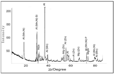
Comparing the phase composition, at 15 min DT, Al was seen as a single phase deposit, which might have been due to an improper bath diffusivity, and to the constituent movement towards the cathodic site, along time 14. In Fig. 4, the CC crystallographic orientation and diffuse phase pattern propagated perfectly, as expected, due to the NP incorporation into the coating bath. X-RD clearly shows Ni and Zn embedded in Al, in the diffractograms trend. Furthermore, Al2O3 incorporation into the bath resulted in the reactive formation of Al(Mn, Ni)Si, MgSi and Al(Mn, Ni)P on the CC, at 30 min DT. One could affirm that there was a significant intermetallic phase that promoted perfect crystal stable conditioning, homogeneity and porosity minimization. The reaction between Ni, Zn, P and Al2O3 caused the grains crystal size orientation. Equally, the improvement in different crystal structures can be related to the grains growth, due to their compactness. In summary, the samples, at different times, gave a good image of the surface structure that was expected within the phase interface.
Coating thickness
Ni-Zn-P-15Al2O3 deposited sample coating thickness values, at different DT of 15, 20, 25 and 30 min, are presented in Fig. 5.
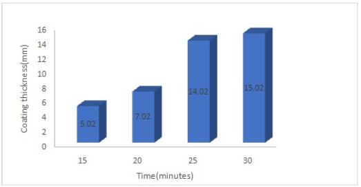
The coated sample at 30 min DT showed a thickness value of 15.02 μm, which corresponds to better coating strengthening capacity than that of 5.02, 7.02 and 14.02 μm, at 15, 20 and 25 min DT, respectively. Accordingly, an increase in DT for Al2O3 particulate enhanced the coating thickness.
HVN behavior
The fabricated coatings HVN values variation with DT are presented in Fig. 6.
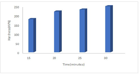
The coatings mechanical ( increased with longer DT. For instance, the produced CC had 180 and 250 HVN, at 15 and 30 min, respectively. The increase in the coatings DT showed a non-linear correlation with (. This means that the reactions that occurred during the ED process were diffusion regulated. The observed result was expected, because the coatings behaved as true compounds. The coated samples at 30 min DT showed higher ( values then those at 15, 20 and 25 min. The ( values were impacted by Al2O3 presence in the electrolyte, with an increase in DT. Moreover, the coatings reinforcement particle was ceramic, of which main feature was the production of strong HVN with a uniform structure. HVN of the coatings, at 15 min DT, was also higher than that of those with lower particulates of reinforced particles, at the same DT, but it was lower at 30 min. This might be due to the coatings changes in the crystal structure and particulates, and in their conditions with DT 16-18. Also, the alloy strengthening effect, at 30 min, might have been responsible for the coatings ( higher peak. Furthermore, the greatest ( value for these coatings, at 30 min, seems to be a result of the Al2O3 content with the DT. In addition, the alloy structural morphology, and the reinforced particles properties in the coatings were the determinant factor for their (. Since these coatings possessed Ni in their matrix, a rise in (, with an increase in Al2O3 DT in the bath, seems to have improved their strengthening properties.
Wear behavior
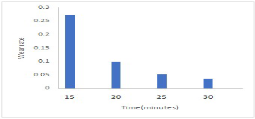
The CC wear variation with DT is presented in Fig. 7. The coatings showed a reduction in wear rate with an increase in DT, since the lowest values were observed at 30 min. In addition, the load bearing capacity and the bond with the alloy might also have caused the coating wear rate reduction with an increase in DT. The increase in the wear resistance due to the reinforced ceramic particles in the MS coatings was also caused by the rise in their average ( values. In general, the obtained results for the coatings wear resistance were excellent, and have also displayed less deformation with an increase in DT, along with a decrease in the surface dislocation and adhered layer 19,20.
Ni-Zn-P-15Al 2 O 3 deposited samples gained mass analysis
Table 2 shows the weight gained from Ni-Zn-P-15Al2O3 CC ED, at different DT (15, 20, 25 and 30 min).
Table 2 Mass gained from Ni-Zn-P-15Al2O3 ED.
| Coating sample | Time (min) | Al2O3 (g) | MS mass (g) | Plating mass (g) | Gained mass (g) |
|---|---|---|---|---|---|
| Ni-Zn-P-15Al2O3 | 15 | 15 | 22.1316 | 22.1958 | 0.0642 |
| Ni-Zn-P-15Al2O3 | 20 | 15 | 15.6854 | 15.7761 | 0.0907 |
| Ni-Zn-P-15Al2O3 | 25 | 15 | 18.4065 | 18.5367 | 0.1302 |
| Ni-Zn-P-15Al2O3 | 30 | 15 | 20.3654 | 20.5221 | 0.1567 |
The obtained CC mass increased with longer DT, since it reached its highest value at 30 min. An improvement in the gained mass with increased DT indicates Al2O3 impact on the CC properties. This finding agrees with 15, who has reported that the nature of the reinforced particles caused the deposited surfaces to bond properly with the substrate.
Electrochemical behavior
Table 3 shows PDP data obtained for Ni-Zn-P-15Al2O3 CC, at 15, 20, 25 and 30 min DT.
Table 3 PDP data for Ni-Zn-P-15Al2O3 coatings at different DT.
| Ni-Zn-P-15Al2O3 DT | Ecorr (V) | Icorr (A/cm2) | CR (mm/year) | Rp (Ω) |
| 15 min | -0.75921 | 0.0039341 | 2.8250 | 68.214 |
| 20 min | -0.75812 | 0.0039339 | 2.8198 | 69.204 |
| 25 min | -0.75800 | 0.0039302 | 2.8188 | 70.104 |
| 30 min | -0.75724 | 0.0039299 | 2.8179 | 71.105 |
The coating reinforced with 15 g Al2O3 particulates obtained at 30 min DT showed the lowest Icorr, Ecorr and CR values of 0.0039299 A/cm², -0.75724 V and 2.8179 mm/year, respectively, and the highest Rp of 71.105 Ω. PDP data indicated that Rp was directly proportional to DT. An improvement in the coatings corrosion resistance properties was triggered by the 15 g Al2O3 reinforced particulates within the MS matrix, thus providing protection. From the data seen in Fig. 8, the CC produced at 30 min DT formed a more stable passivity than that of the ones at 15-25 min, due to the increase in the number of particles deposited on the cathode, at an increased E.
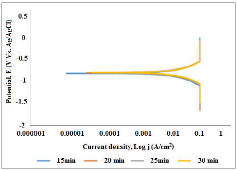
In addition, lower E resulted from the smaller covered surface area, and from the Al2O3 adsorption effect, along with the ionic transport by the NP on the substrate 15-21.
Clearly, the polarization curve for the coating, at 30 min DT, shows a wider passive region and lower J. OCP, with DT variations, for the coating deposited onto MS in 3.65% NaCl is shown in Fig. 9. Positive similarities were observed with a shift towards the positive region. The shift towards a more negative E showed that MS had a unique dissolution, due to the absence of passivation in some regions with less coverage, while the movement towards the positive side indicated the formation of covering films.

Conclusions
Ni-Zn-P-Al2O3 CC was successfully developed on MS, with a DT range from 15 to 30 min, and showed a strong bond and adhesive properties.
A fine grain structure and less nucleation sites and crystals, which were attributed to the reinforced NP, were obtained at 30 min DT.
The diffractive patterns showed the presence of diffusive intermetallic phases that were significant to the surface modification and protective propagation.
The wear loss was drastically reduced, with a lower dislocation trend (0.003 g), due to the excellent particles interaction within the cathode surface. HVN grew spontaneously, as a result of ( metaphysics.
The best corrosion resistant sample was obtained for a developed DT difference of 30 min, with 71.105 Rp.
Authors’ contributions
O. S. I. Fayomi: conceptualization; methodology validation, supervision. A. E. Olawuni: investigation; writing. I. G. Akande: analysis; interpretation.
Abbreviations
Al2O3: aluminum oxide
ASTM: American Society for Testing and Materials
C6H5Na3O7.2H2O: trisodium citrate dihydrate
CC: composite coatings
CR: corrosion rate
DT: deposition time
E: potential
Ecorr: corrosion potential
ED: electrodeposition
EDS: energy dispersive spectroscopy
H3BO3: boric acid
HCl: hydrochloric acid
HVN: mean microhardness values
I: current
Icorr: corrosion current density
J: current density
LSV: linear sweep voltammetry
MS: mild steel
Na2CO3: sodium carbonate
NaPO2H2: sodium hypophosphite
NC: nanocrystalline
(NH4)2SO4: ammonium sulfate
NiSO4.6H2O: nickel sulfate
NP: nanoparticles
OCP: open circuit potential
P-Al2O3: phosphorus-aluminum oxide
Pc: phytochemical
PDP: potentiodynamic polarization
Rp: polarization resistance
SEM: scanning electron microscopy
SiO2: silicon dioxide
T: temperature
TiO2: titanium oxide
X-RD: x-ray diffraction
ZnSO₄: zinc sulphate
Symbols definition

